 06/06/2011
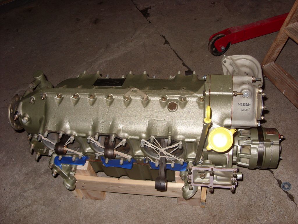
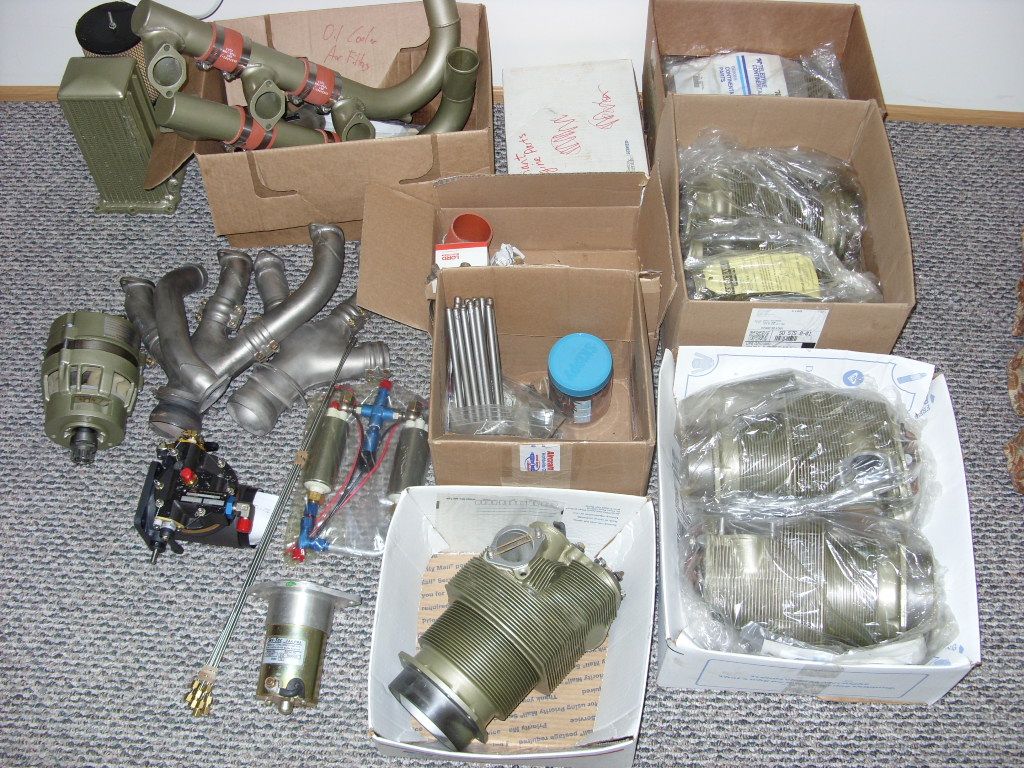
The TCM IO-360-C is the second engine block for the SQ2000. The complete engine with accessories, without ignition, was purchased for $8k from Matt Kwiatkowski of Romeoville, IL who gave up on his Defiant project. He is an A&P and had about all the parts re-manufactured. The 0 SMOH engine comes with Airflow Performance fuel injection. The dual Light Speed LSE ignition from the Franklin will be re-used. I got the TCM since I prefer smoother 6-cyl engines over Lyc. IO-360 four bangers. The engine came in parts as an experimental without certified plate.
04/11/2012 post note: Except for the basic TCM IO-360-C block/cylinders the engine is quite different from a certified engine - electronic ignition, Airflow Performance fuel injection, dual electric fuel pumps, 12V solenoid fuel primer, remote oil filter/cooler, non standard engine mount, custom exhaust headers, cooling plenum with electric cooling fan, tight sealed cooling air flow, lightweight experimental alternator...
 06/15/2011
The job is not just installing the Continental. Took a week to dismantle the Franklin.
Lining up the new engine for building a new mounting. Turned out the supplied basic mount frame part was for another engine.
1. I weighed the dry engine with starter, alternator and
LORD mounts and it came out to about 315 lbs total. Not bad. I don't
know where TCM gets 332 w/o accessories. WIll see how the W&B compares
with the old Franklin. It will have a similar engine mounting bed.
The engine mount bed from the old Franklin was only about 11 lbs.
I expect the new one to be similar.
2. I put the top half of the cowling on to see and it looks like it will
fit with minor mods. But composite is amineable to changes.
I plan to make a composite plenum baffle - for exact fit.
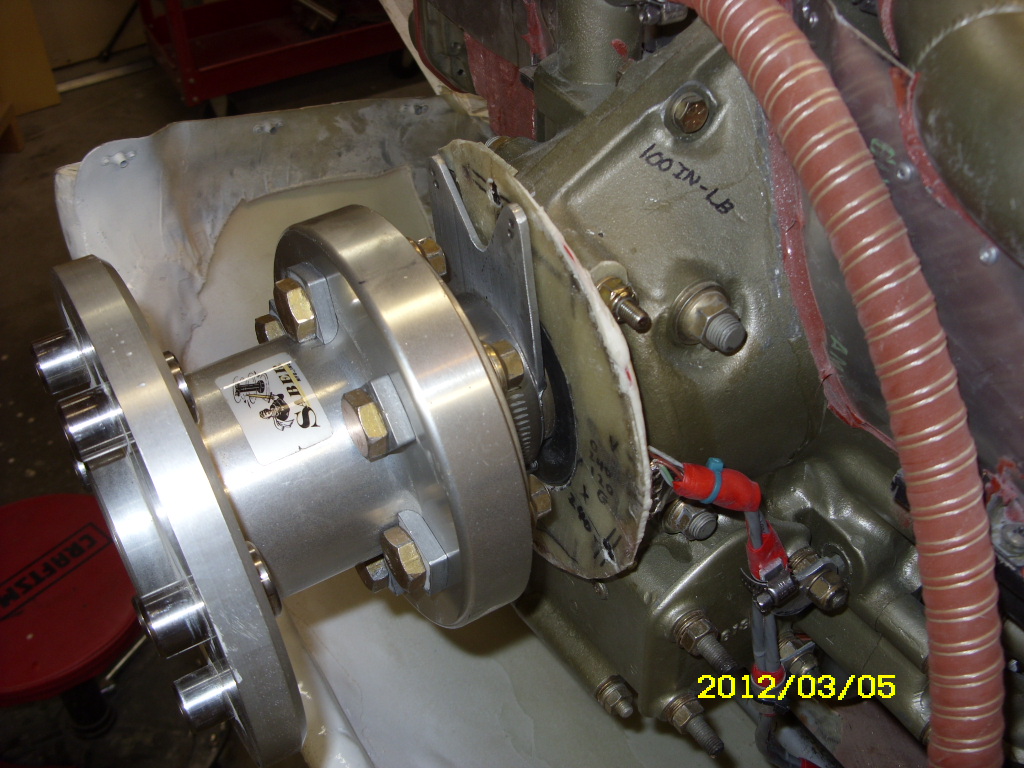
3. The prop extension is transferable from the Franklin to the
TCM - same flange hole dimensions.
Waiting for some mount metal parts...
 07/03/2011 - TCM external oil cooler adapter
My old Franklin external oil cooler/filter was better positioned for cooling than the engine mounted Continental oil cooler so I decided to reuse it. I carved a 3/8 aluminum adapter plate with TCM cooler bolt pattern and added inlet/outlet nipples.
This is the second engine frame I built from scratch. I didn't have a mounting with bushing holders to fit so holders were improvised from 5/8 aluminum blocks bolted to improvised brackets welded to the frame. The mount frame is considerably lower due to the larger LORD mount bushings.
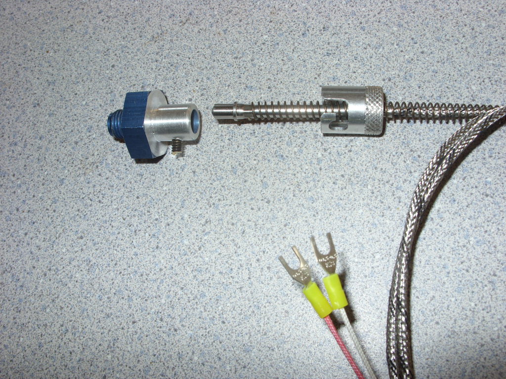 08/02/2011 - bayonet CHT probes.
Inexpensive bayonet probes are available direct from manufacturer distributors like
the IMS company. Their Type J 48" lead and 96" inch lead probes are $22 and $27.
You can order them directly from
the IMS website
part number page. The 48" and 96" catalog numbers are 147027 and 147028 - just scroll down.
You can purchase a CHT probe adapter to screw into your 3/8 bayonet hole from Aircaft Spruce for $19.
If you have a small lathe you can make the one shown at left from AN919-5D reducer ($3.50 from AS). Just drill a 1/4
hole and machine down the other end until the receptacle fits over it. Then drill a 7/64 hole and start a
6/32 thread tap to jam in a 6-32 brass screw which you cut off just to leave the stub.
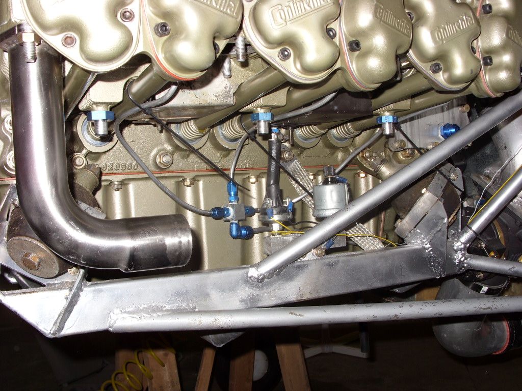
 08/29/2011 - Fuel Injection & Engine Mount
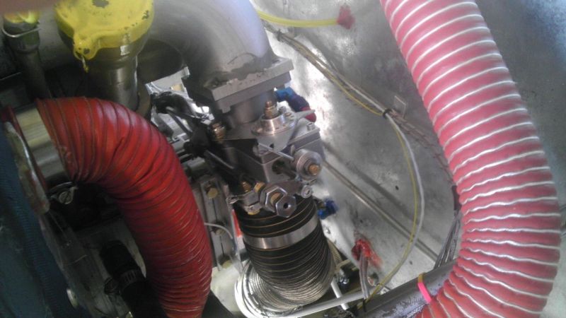
The TCM top intake manifolds and low engine mounts posed some challenges.
1. I use the big lower NACA scoop for mounting a generous airfilter. Its a good place to get decent ram air and prevent rain intake. The Airflow Performance FM- 200 fuel controller is big. There is no room for it on top of engine with the manifolds and the linkage would be difficult. I mounted it rigidly on the firewall with aluminum tubing leading to the engine. The Silicone Hose Double Hump Coupler is flexible enought to allow for engine vibration and yet sturdy enough to maintain manifold pressure. The tubing elbow is held rigid to the engine with two curved brackets mounted to the engine and attached to the tube by two separate hose clamps shown on top.
2. Typical certified aircraft have much more vertical fireweall room for engine mounts than the SQ2000 or other canards. The Lycoming compact firewall engine mount has an advantage in that respect. The TCM engine mount rubbers required the engine mount hardware fairly low resulting in shallow triangles with larger stress on the tubing. I added extra reinforcement tubing both sides as shown. This made the TCM engine mount 18 lbs compared to the 11 lb Franklin mount. Luckily I am not using the TCM oil cooler which would get in the way of the reinforcing tubing.
 09/01/2011 - Airflow Performance fuel pump.
Airflow Performance fuel pump assembly that came with the engine fuel injection
was assembled with AN fittings and tubing and looked like giant spaghetti.
I rearanged it into a compact package by fabricating a couple aluminum manifolt
fittings.
04/25/2012 Note: It appears the pump set is assembled from automotive inline pumps
available from aftermarket suppliers (see for example
Facet-Purolator FEP2000 In-Line Fuel Pump ) with the added relief valve.

Most of the plumbing and engine assembly is in place. Some ignition work to go.
 I added a purge valve to help with engine shutdown and to purge vapors on hot starts.
The valve is not the mechanical lever operated diverter valve that Airflow Performance
sells. It is a simple electrical pressure relief valve (Parker 12V solenoid valve)
that relieves the pressure into the right wing tank - much cheaper and easier to install
with a electrical button activation instead of routing a special control cable.
Will see how it works.
I added a purge valve to help with engine shutdown and to purge vapors on hot starts.
The valve is not the mechanical lever operated diverter valve that Airflow Performance
sells. It is a simple electrical pressure relief valve (Parker 12V solenoid valve)
that relieves the pressure into the right wing tank - much cheaper and easier to install
with a electrical button activation instead of routing a special control cable.
Will see how it works.
2012/04/03 Note: An electric version of a diverter purge valve is available from Valve Store online. It is much easier to install electric wire than run a separate cable for the mechanical "Airflow Performance" valve.
In fact seems that an electric diverter valve would be safer after reading Airflow
Performance warnings
about the mechanical valve cable getting loose and causing a hazard.
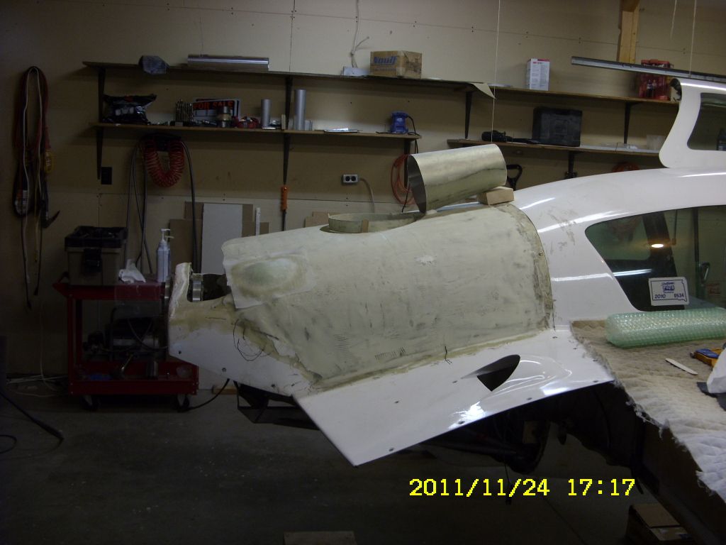
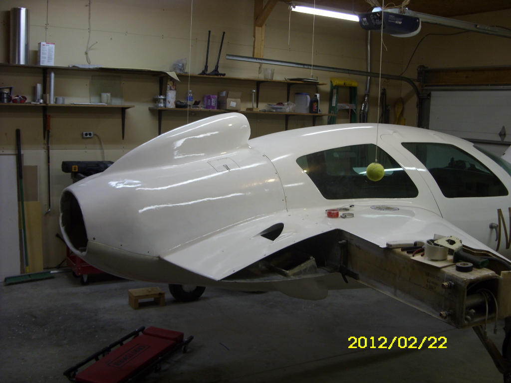
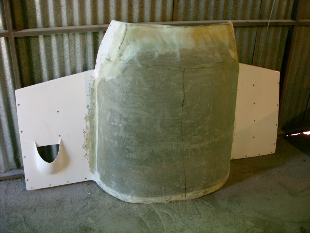 Starting on the cowling mods showing upper cowling part.
I simply cutout the old section that did not fit
and put a newer section using a piece of sheet metal for a form.
However the end part of the cowling turned out poorly shaped because sheet
metal cannot be shaped to properly curve at end. (That piece was cut out
and reshaped as shown below.)
Starting on the cowling mods showing upper cowling part.
I simply cutout the old section that did not fit
and put a newer section using a piece of sheet metal for a form.
However the end part of the cowling turned out poorly shaped because sheet
metal cannot be shaped to properly curve at end. (That piece was cut out
and reshaped as shown below.)
Prior to this I took a chance on some surplus Velocity cowlings from David Hanson hoping to adapt them here but their shape and size was totally wrong for the engine and the fuselage back end.
 09/28/2011
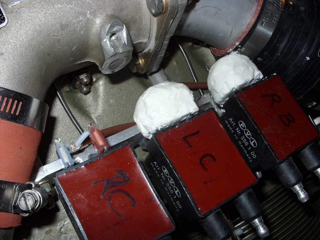
To avoid LSE coil spade connectors vibration failure I encased them with glass bubble epoxy mix.
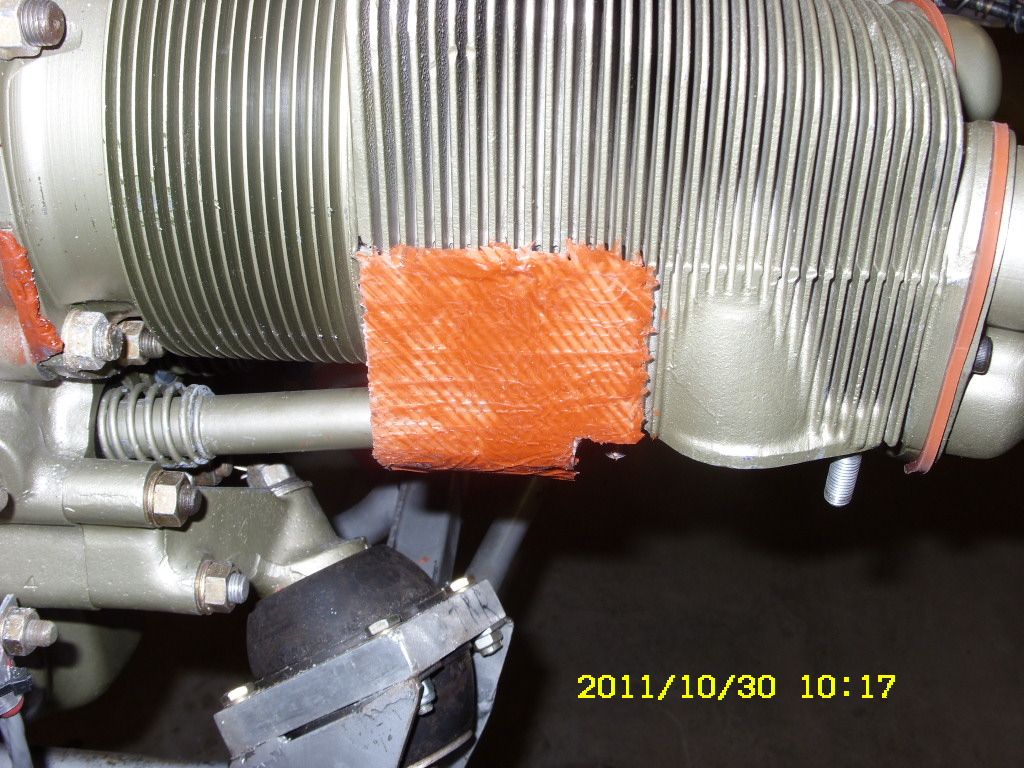 I am adding RTV/GlassBID cylinder baffle guides for more
precise air flow control. Wasting less air flow will require a smaller cooling airscoop intake.
I am adding RTV/GlassBID cylinder baffle guides for more
precise air flow control. Wasting less air flow will require a smaller cooling airscoop intake.
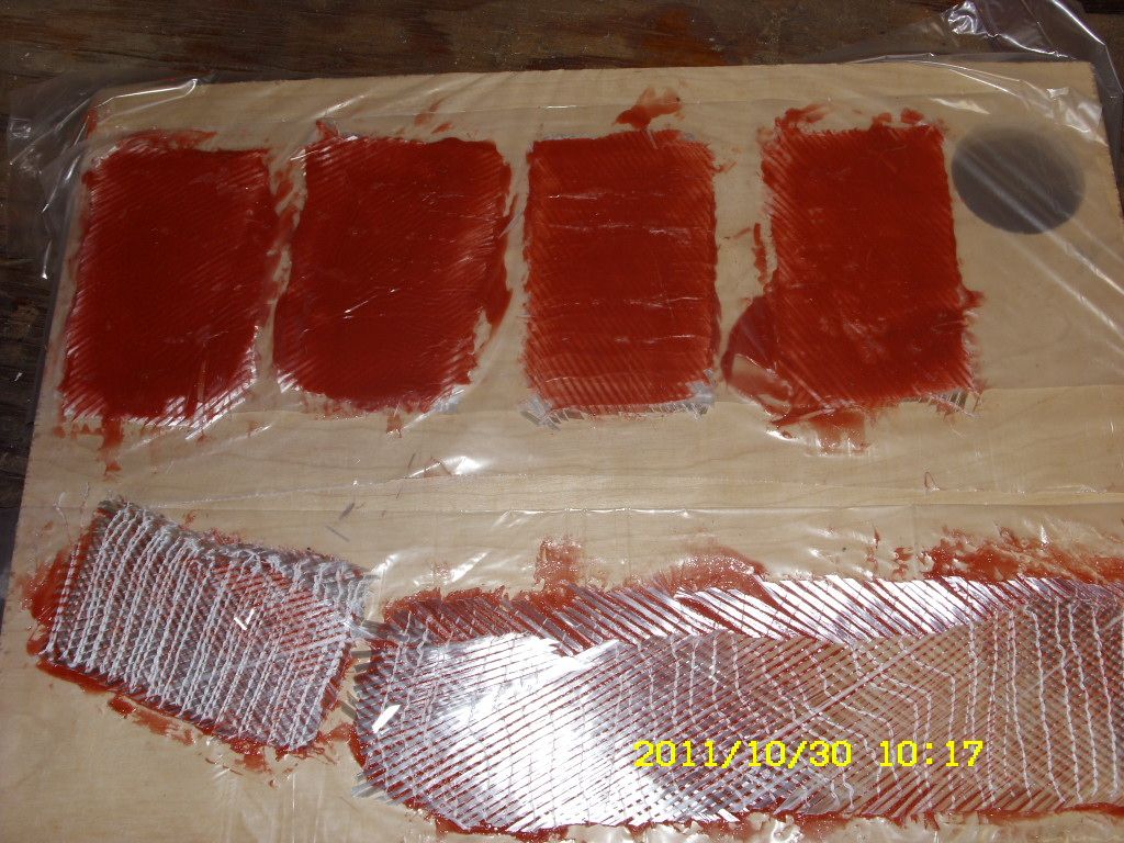 Initially I made the RTV/BID covers by applying RTV to both sides of BID same time. But
that makes it difficult to apply to the cylinders since the gooi stuff stretches out
of shape and requires more trimming when cured. I changed it to applying the thin,
RTV outside layer first, turning it over and let it cure. Then its easier to precut to
more precise shape, apply the second thicker RTV layer (a little more than 1/16 or 2mm).
Initially I made the RTV/BID covers by applying RTV to both sides of BID same time. But
that makes it difficult to apply to the cylinders since the gooi stuff stretches out
of shape and requires more trimming when cured. I changed it to applying the thin,
RTV outside layer first, turning it over and let it cure. Then its easier to precut to
more precise shape, apply the second thicker RTV layer (a little more than 1/16 or 2mm).
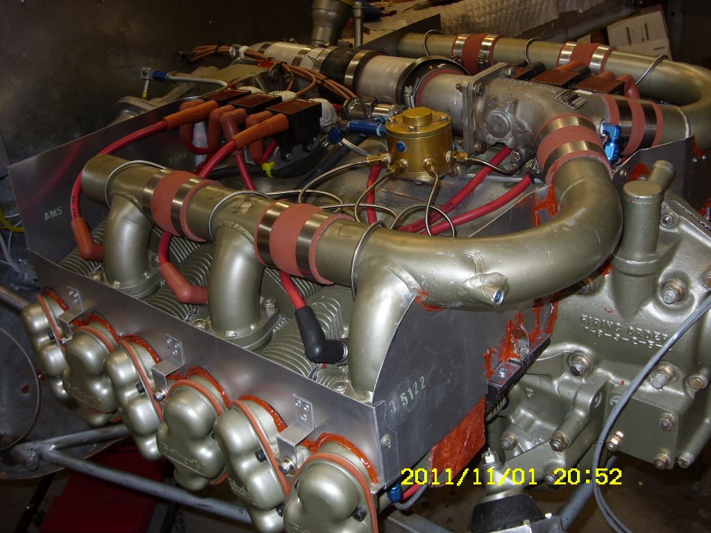 11/01/2011.
The aluminum lower part of the planum is done. Gaps were sealed with RTV.
 The intercylinder air gaps are more tightly closed in with aluminum plates and
RTV. The ignition wires go through gromets to eliminate air leaks.
The original Continental intercylinder baffling was designed for more
generous and less efficient air flow.
The intercylinder air gaps are more tightly closed in with aluminum plates and
RTV. The ignition wires go through gromets to eliminate air leaks.
The original Continental intercylinder baffling was designed for more
generous and less efficient air flow.
The tighter air sealing and separate oil cooler should require a smaller
air intake scoop.
Aircraft engines are designed for downdraft cooling and I see no advantage to
updraft cooling except aesthetics - a bottom air scoop is not as noticable.
Larger Velocities have successfully integrated top dual NACA cooling scoops. But
there is no room on the SQ2000 roof for NACA scoops. A stick out scoop should be
at least as effective and should not have more drag than my previous Franklin
engine with dual side scoops.
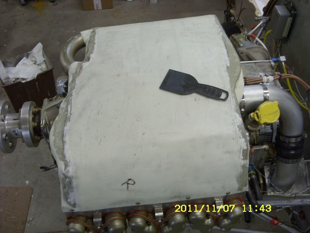 11/07/2011. Plenum top cover.
I used simple sheet metal form covered with plastic for laying the fiberglass. The fiberglass conforms to odd shaped portrusions on the engine to give a good air seal. It is made up of only two layers BID sandwiching a thin layer of glass bubble epoxy (the white colour). This creates a relatively rigid and lightweight part for places where stiffness is desired without great structural strength. A fairly uniform bubble epoxy layer can be made with a serated spreader.
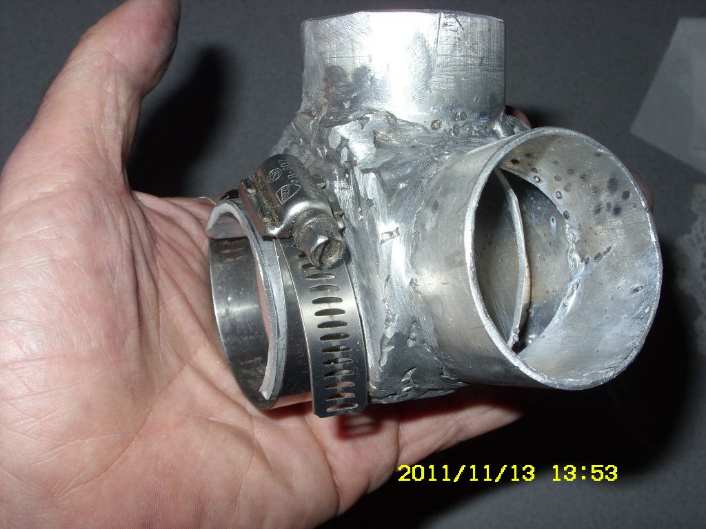 11/13/2011. Cabin heat muff.
With experimentals undercowl space is at premium. Will this tiny cabin heat muff work? Its only half moon. But aluminum has high heat conductivity and I put two extra heat exchange fins in there. My aluminum welding is not the greatest but high precission is not needed here.
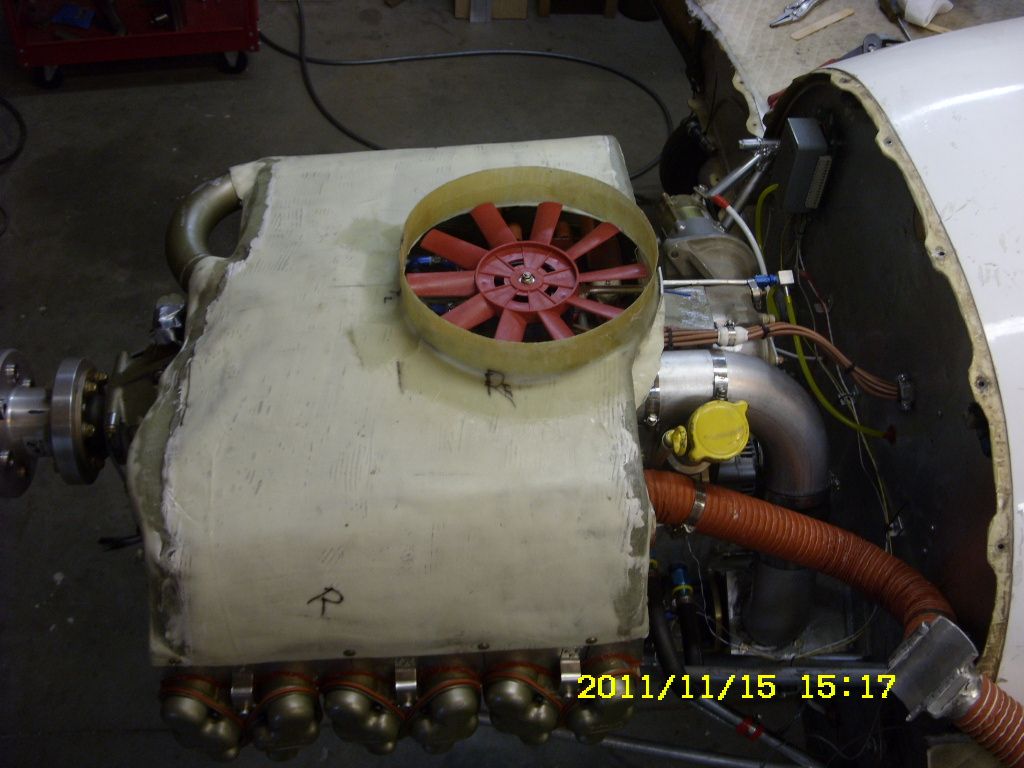
With pusher downdraft cooling a fan will help with those long hot taxi times and possibly when climbing. The separate oil cooler intake scoop has its own (smaller) fan.
Starting on the air intake system with optimal 11 degree, area doubling diffuser cone. It may be more visible on top but not necessarily more drag than one mounted on bottom out of sight.
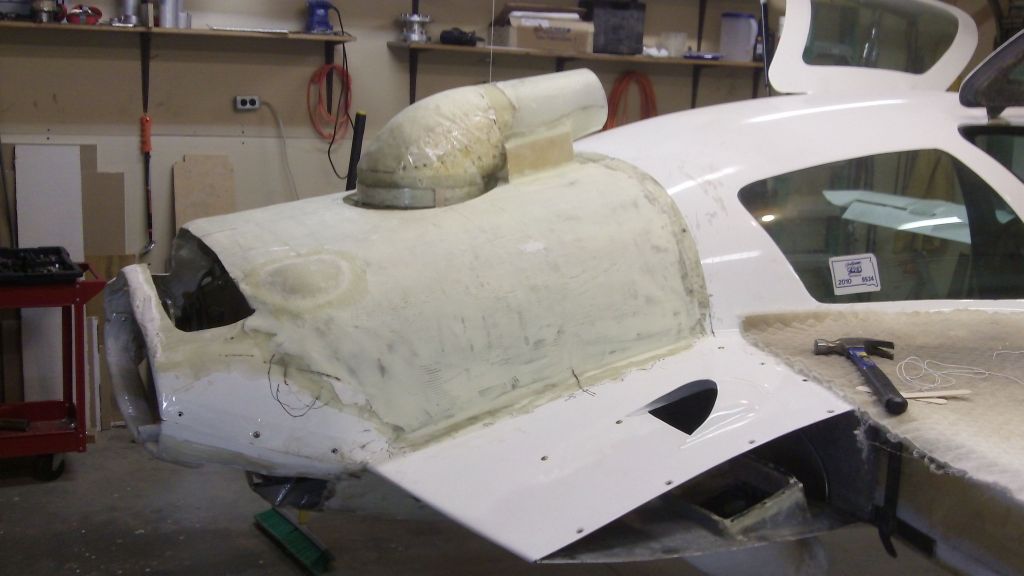
I used standard expanding foam to shape the intake scoop duct. The stuff leaves too many big bubbles which had to be repeatedly filled when shaping. A startup fiberglass layer is shown on top. The upper part is separate from bottom part and the gap is sealed with a circular RTV-BID baffle strip. The final product will look more streamlined when finished.
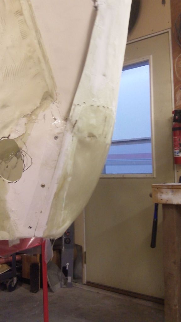 12/19/2011. Gravity parabola shaping
Finaly shaping the converging rear end of cowlings. I did not want to spend a month making foam forms so I exploited the parabolic gravity shape of suspended objects. The upper and lower BID parts cleave by epoxy surface tension. Peel ply cannot be applied in normal way so I simply wetted the peel ply first and then gently attached it to the surface and it clings to it by surface tension. I have two BID layers at once which can pose a problem with air bubbles between the layers. The cure is to simply poke holes in the bubbles with a pin. Surface tension and gentle stroking with mixing stick does the rest.
 12/27/2011. LSE Ignition crank plate
More ignition work while waiting for other parts. For the crank sensor plate a thin flat layer of two BID (after cured for days) is cut to C shape and attached to the crank with small sheet metal formed bracket pieces with epoxy and then covered over with thin BID for reinforcement. Clearance on this crank is less generous than the Franklin.
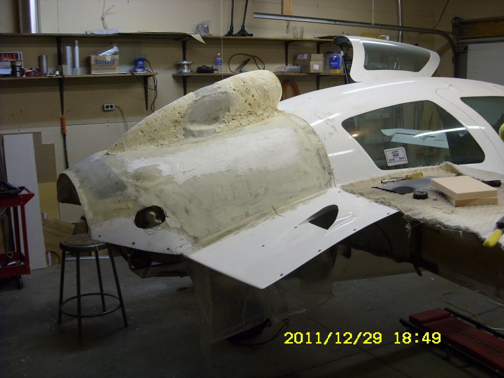 The top mounted air scoop taking more streamlined shape.
 Looking better after a top DIB layer and more microbaloon filler and sanding.
 And the cowling with paint on. My finishing skills do not exactly
produce a candy finish but decent enough. The paint is
acrylic urethane 3 part mix - quite espensive (about $150/qt) but very good stuff. My small
2hp compressor cannot handle regular spray guns. But LPLV (low pressure low volume) spray
guns - available on the market - add a little extra spray time.
And the cowling with paint on. My finishing skills do not exactly
produce a candy finish but decent enough. The paint is
acrylic urethane 3 part mix - quite espensive (about $150/qt) but very good stuff. My small
2hp compressor cannot handle regular spray guns. But LPLV (low pressure low volume) spray
guns - available on the market - add a little extra spray time.With the paint job, the stream lined air duct intake looks more in place. The TCM IO-360 is a "fat" engine compared to the Franklin. The induction tubing is on top adding to height and width - the extra rear engine "bubble" is showing. I don't see any other efficient way mounting the engine without a top duct intake. Of course the included engine cooling fan feature will be a valuable asset for long hot taxiing.
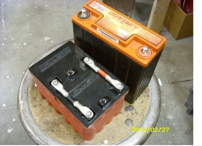 While working at the engine I decided to try the new LiFePO4 Ballistic EVO2 batteries
to replace the rear PC680 cranking battery.
It required two of the lightweight Ballistic 12 cell batteries to get me cranking needed.
For more details click here..
I would like to replace the front 24 lbs PC-925 battery but the extra weight is
needed for ballast.
While working at the engine I decided to try the new LiFePO4 Ballistic EVO2 batteries
to replace the rear PC680 cranking battery.
It required two of the lightweight Ballistic 12 cell batteries to get me cranking needed.
For more details click here..
I would like to replace the front 24 lbs PC-925 battery but the extra weight is
needed for ballast.
 Here is the Hall effect, crank sensor, circuit board and the magnet holding bracket
I made from fiberglass and aluminum for the LSE. It is similar to the one I made for the Franklin engine.
It is far more compact than stock pieces that LSE supplies. The space here is a little
tighter than on the Franklin. The engine is essentially done and should run with some fuel.
Here is the Hall effect, crank sensor, circuit board and the magnet holding bracket
I made from fiberglass and aluminum for the LSE. It is similar to the one I made for the Franklin engine.
It is far more compact than stock pieces that LSE supplies. The space here is a little
tighter than on the Franklin. The engine is essentially done and should run with some fuel. Will probably wait for more steady good weather before moving the plane back to the hangar to start the engine. A few minor things can still be done in the garage.
It seems a bit tricky starting - especially restarting after it warms up a little. I am used to the carb or TBI where it starts right away. Also concerned about the oil pressure. It shows 45 psi tops and then drops down to 30 after while. But these maybe things to tweak out yet. (Note: seems the drop was initially due to air in the filter and cooler.)
Cold starting is not easy but after shut off it is near impossible. It did not come with Continental fuel injection but with experimental "Airtflow Performance", Bendix like fuel injection and with dual electric fuel pumps instead of any engine driven fuel pump. Restarting procedures used with engine driven fuel pumps do not work here. The procedures suggested in the "Airflow Performance" manual with the two electric pumps are probably for Lycoming engines with bottom induction where the fuel can puddle. As is, this setup seems to need a priming system.
I have rearranged the purge valve to be used as a primer. But it turns out the "PARKER 12V SOLENOID VALVE" (20CC02PV4B2B) has a 24v solenoid even though Wicks sells it as 12V. It works with low or no fuel pressure but not with the 25-30 psi pressure here. The valve is rated to 60 psi.
I have ordered and will try some Chinese solenoid valves with 12V, 100psi ratings. Here is a source of a 12V valve The Valve Store
But all this is a big delay getting the thing in air.
04/09/2012 Managed to get a Chinese solenoid valve (12V DC 1/8" 2W025-06) on eBay. Fortunately it had a solenoid that fit on the Parker valve with a little adjustment giving a healthy snap when turned on. It saves time mounting a new valve with different dimensions.
After accounting for the two new lighter LiFePO4 batteries (22 lbs savings) the new installation did not increase the engine compartment weight. In fact considering the higher TCM engine mount weight (19 lbs for the TCM and 11 lbs for the Franklin) and probably couple pounds for the added engine cooling fan, the TCM IO-360 seems about 10 lbs lighter than the Franklin. However the CG of empty aircraft has moved back about 1.25" - the Franklin had some weight in the vibration damper/flywheel combo "up front" so was set about 2" more forward and had a longer crankcase neck to the prop flange.
The weather here was blustery for several days. But today winds were half decent to push the plane out of the hangar. The primer really helps with the cold start - about couple of cranks. It seemed to help with hot starts but not as much. But I found a routine that seems to work better. Full throttle, full lean cutoff, crank and pull the throttle and mixture on when it fires. The fuel controller seems to give too much fuel. Engine runs quite rough unless its near half mixture settings. May need a smaller controller orifice.
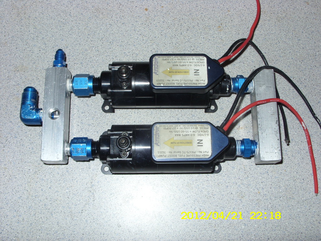 04/20/2012 Andair Fuel Pumps.
 The AP fuel pump assembly is fairly complex with lots of unusual connections and external pressure control valve. It came with the kit. I decided to simplify things a bit and purchased Andair PX375-TC pumps - which AP also sells. They are expensive but straight forward plumbing with built in bypass and relief valve AND about half the weight and size. It reduced 2 lbs from aircraft weight. The AP fuel pumps are up for sale on the aircraft flea-market page in case someone needs a replacement or a less expensive set.
04/24/2012 Got them installed. Now do not have a fuel smell that was present with the previous complex setup with more potential leak sources. The static pressure reads 26 psi instead of the 32 with the previous pumps. Wonder if that was the source of excess fuel feed. Will find after next startup. The surprise is the pumps are fairly noisy for the small size. Sound like a cordless drill.
Got the bird up in the air first time today with the TCM IO-360. The engine ran smooth up to the red line (2800) - smoother than the Franklin - and stayed cool all the way (it was 70F ground OAT). It seems the upper air scoop and the tight engine baffling is doing a good job. The oil pressure was down a bit 28psi (30-60 is normal). Will have to check the gauge accuracy.
05/02/2012 Found that the oil pressure relief valve can be adjusted by inserting washers behind the spring. That hopefully will fix the low oil pressure. I also decided to move the oil filter to the oil screen position with an FM C6SC adapter available from aircraft parts suppliers. The current oil filter position, just before the oil cooler, does not do a good job since in the TCM the Vernatherm valve does not send oil to the cooler until the oil reaches 180F and a lot of oil flow got unfiltered.
05/09/2012 After above adjustment today's flight showed 32-46psi OP - which is within specs. The engine stayed cool in climb and in cruise averaging about 375F (190C) with about 388F (198C) ocasional peak. Ground OAT was 78F. Recommended cruise max is 380F - with 460F limit. Forgot the OT but it was always in the green.
I still have hot starting problems and some rough idling issues with the AFP FI. Cold starting with the primer is great but hot starting is really a pain. I worry about going cross country and not being able to restart after fueling.
On another note: I had plug and piston carbon fouling problems on both the previous Franklin 8.5 pistons and with this TCM. In the first case, the plugs were too cold heat left over from the older high compression Franklin pistons and again for the TCM too cold plugs. Caution: don't just get real hot range plugs. Too hot range plugs can act like glow plugs and cause detonation to ruin your engine.
Rotec TBI-48-4/5
 I also tested a Rotec TBI on the TCM. Turns out that it runs too
lean and consequently rough so I have removed it until some later date when I have
time to experiment with it. The factory sent me instructions how to enrich the spray
bar component. One thing I cannot quite figure out about the TBI: it is mounted just
about top of the wing tank level. But when I turned
the fuel pumps off the engine still kept running. It did that for the Franklin when
I had it. But the TBI on the Franklin was mounted about 15" below the tank and some
gravity pressure could be expected.
I also tested a Rotec TBI on the TCM. Turns out that it runs too
lean and consequently rough so I have removed it until some later date when I have
time to experiment with it. The factory sent me instructions how to enrich the spray
bar component. One thing I cannot quite figure out about the TBI: it is mounted just
about top of the wing tank level. But when I turned
the fuel pumps off the engine still kept running. It did that for the Franklin when
I had it. But the TBI on the Franklin was mounted about 15" below the tank and some
gravity pressure could be expected.
08/09/2012 Update: One of the FI electric fuel pumps failed on run up test yesterday and the AFP FI would not restart the hot engine on the other fuel pump. Had to be towed back to hangar ($47). Contacted Andair who said they will replace it - probably take 3 weeks from UK.
So I mounted the Rotect TBI back after making the manufacturer suggested mods (ream the holes on the spray bar to larger size). On static hangar tests the engine now gets plenty of fuel and runs normal but run a little too rich now as I have to lean it about half way for normal. However it was 90F+ in the hangar. The big problem now is massive icing buildup in the intake pipes. The pipe just above the TBI gets cold like refrigeration tubes after just a minute of running. Tried to taxi to runway (08/10/2012) and it got extremely rough and eventually quit. The TBI needs to be designed with the right holes on the spray bar. Rotec offered to mod the TBI to more correct spary bar holes for me. So the TBI was returned to Australia for the mod.
08/17/2012
So that left me without a running fuel system - the Andair fuel pump sent back to England and the
Rotec TBI back to Australia. So I put my original AFP fuel pump
setup back together again to make flight possible in meantime. Tried to be carefull but had to fix
one plumbing leak in the fuel pump setup.
08/19/2012
Took it up today for short while. Ran ok considering some turbulence. CHT was up to 392F (200C)
during climb - 80F OAT. Need to adjust left wing tilt, since it seemed to rotate to right.
08/23/2012
Fixed wing tilt and took it up for over an hour. No problem with CHT or OT. but there is a continuing
engine vibration problem especially at more throttle. Got to fix it.
08/27/2012
http://www.sacskyranch.com/vibm.htm indicate that a malfunctioning hydraulic lifter could cause vibration.
So I took all the lifters out and took them apart. Found one that was stuck with some dirt.
Opened all the lifters, cleaned and oiled them. Reasembled it and its a happy engine now.