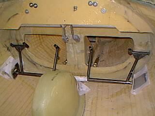
 Showing pedals glassed in. The RH pivot was too close to rightmost
pedal (interfering with rotation - was not symetric to left side) and
I welded a 1/2" pipe extension to the main horizontal shaft.
Showing pedals glassed in. The RH pivot was too close to rightmost
pedal (interfering with rotation - was not symetric to left side) and
I welded a 1/2" pipe extension to the main horizontal shaft.
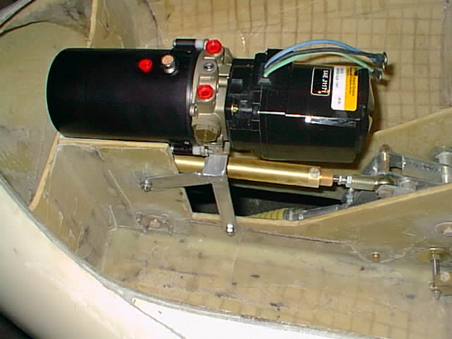 A little bit of welding makes a neat mounting bracket for the RG pump.
The upper bolt mount simply goes on same bolt as NG cylinder pivot
bolt. The lower bolt mount goes through the NG side plates foam. The
sandwiched foam around bolt was removed there with a Dremel type tool
and the space floxed in for crush protection and more rigid
support.
A little bit of welding makes a neat mounting bracket for the RG pump.
The upper bolt mount simply goes on same bolt as NG cylinder pivot
bolt. The lower bolt mount goes through the NG side plates foam. The
sandwiched foam around bolt was removed there with a Dremel type tool
and the space floxed in for crush protection and more rigid
support.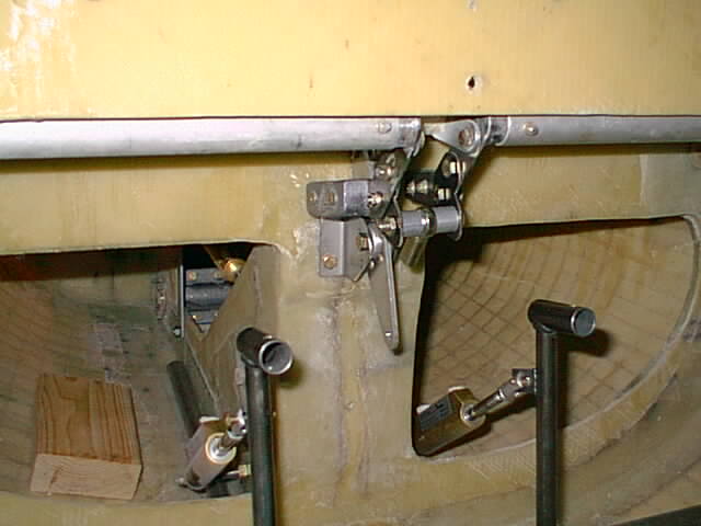 Since we are installing yokes instead of sticks, the elevator reversing belcrank
was installed on the FS-37 bulkhead.
Since we are installing yokes instead of sticks, the elevator reversing belcrank
was installed on the FS-37 bulkhead.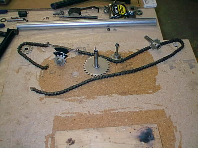 To construct the yoke layout it helped to make a template using particle board
with drilled holes to hold the sprocket positions before welding.
To construct the yoke layout it helped to make a template using particle board
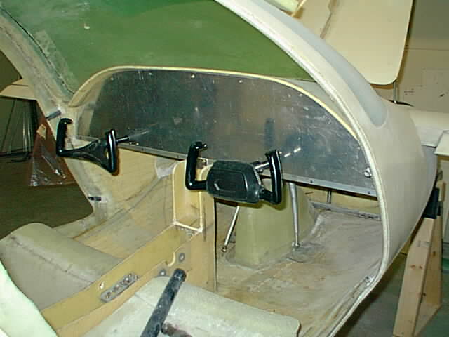
with drilled holes to hold the sprocket positions before welding.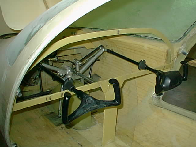 And finally the yoke is roughly in place. This isn't a Leggo job. It does not look
like the Cessna original. Plenty of planning; calculating angles, distances, mechanical
arm ratios; measuring; welding; etc. -
umpteen hours. I got 3" yoke forward motion from the 1.75" travel of the elevator
belcrank position. 3" is probably less than on a Cessna but is sufficient considering
the lower seating position in the SQ2000.
And finally the yoke is roughly in place. This isn't a Leggo job. It does not look
like the Cessna original. Plenty of planning; calculating angles, distances, mechanical
arm ratios; measuring; welding; etc. -
umpteen hours. I got 3" yoke forward motion from the 1.75" travel of the elevator
belcrank position. 3" is probably less than on a Cessna but is sufficient considering
the lower seating position in the SQ2000.
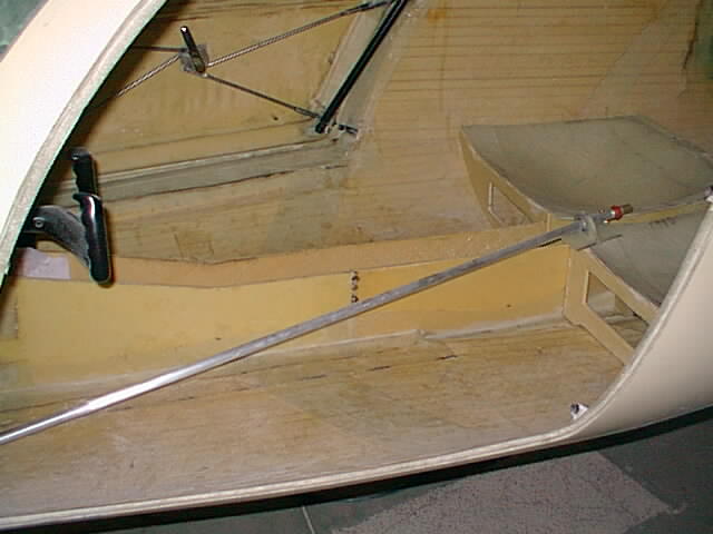
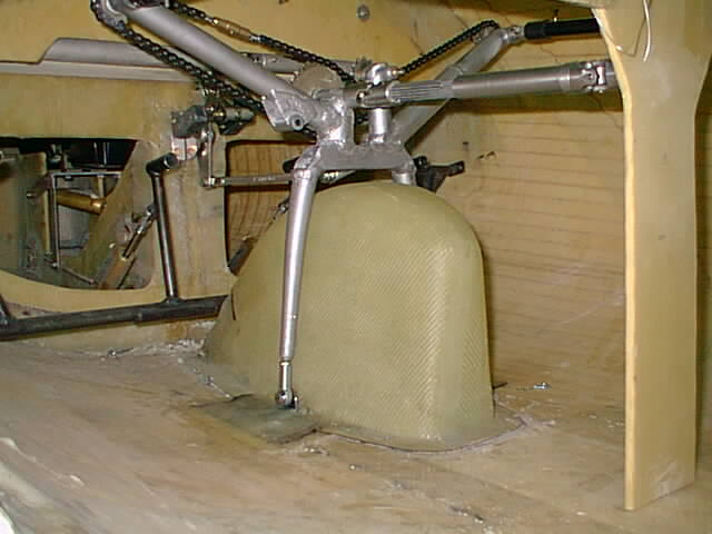 This shows the yoke pivoting saddle to get around the nose gear wheel well.
The elevator reversing bellcrank is connected in front of the yoke assembly just
above top of the wheel well with a rod and two rodend bearings.
Two 1/4" rod end bearings mount the yoke assemply to the floor onto two pieces of
angle iron glassed to the floor. The bottom part of the yoke is from a bicycle fork
welded to a piece 1" square tubing.
This shows the yoke pivoting saddle to get around the nose gear wheel well.
The elevator reversing bellcrank is connected in front of the yoke assembly just
above top of the wheel well with a rod and two rodend bearings.
Two 1/4" rod end bearings mount the yoke assemply to the floor onto two pieces of
angle iron glassed to the floor. The bottom part of the yoke is from a bicycle fork
welded to a piece 1" square tubing.The telescoping universal joint transfers the rotational motion aft to the ailerons through a series of bellcranks and drive shaft (3/4" aluminum tubing with 2 U joints) in center - to be done yet. The telescoping shaft is available from www.sdp-si.com - part number A 5X 8-SE3216 (a meassly $170). Be sure to order from online website or they charge $15 more (without warning) for talking to them on the phone.
(04/02/02 Update: After responding to the company's customer followup letter and mentioning
the problem, they refunded me the $15 difference. I recommend browsing through their website
for your need of miscelaneous gears, pulleys, shafts, etc, etc.)
I also decided to take the shaft and have a local machine shop bore a 3/8 hole in inside spline
and shave the outside sleeve down to 7/8 and replaced the U-joints with aircraft grade flexible
U-Joints. That adds another $175 to the cost but cuts the weight of the U-joint assembly in half
down to 1 lb.
I have a small lathe for machine work but it was too small for the spline parts.
All in all the yoke control adaptation cost me about $800 extra.
Maybe I can sell some of the factory stick parts etc.
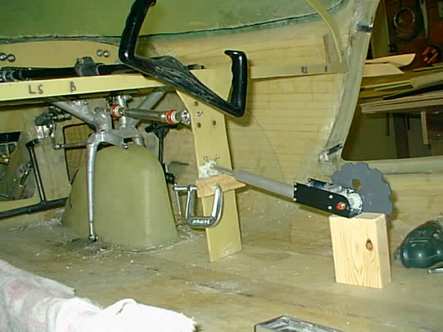 Photo shows modified telescoping u-joint and now attached to the compound
bellcrank (behind vertical console plate) that took several hours to fabricate
with my little lathe. The trim control and the nylon bushing for
the spring "compander" is lined up and floxed into position for minimum
lateral action forces.
Photo shows modified telescoping u-joint and now attached to the compound
bellcrank (behind vertical console plate) that took several hours to fabricate
with my little lathe. The trim control and the nylon bushing for
the spring "compander" is lined up and floxed into position for minimum
lateral action forces.
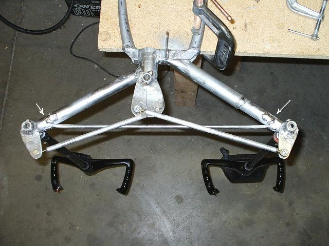 04/06/04 postbuild modification: I found the Cessna chain/sprocket combo had too
much play and modified it to rod and bearing assembly as shown. The yoke cranks
are 2" radius and the main shaft crank is 2.5" radius. That gives the yokes
about 100 degree travel for the 90 degree main shaft. Note the travel limiters
for the yoke cranks to prevent dangerous overturn.
04/06/04 postbuild modification: I found the Cessna chain/sprocket combo had too
much play and modified it to rod and bearing assembly as shown. The yoke cranks
are 2" radius and the main shaft crank is 2.5" radius. That gives the yokes
about 100 degree travel for the 90 degree main shaft. Note the travel limiters
for the yoke cranks to prevent dangerous overturn.
 The ailerons are connected to the yoke with 3/4 aluminum tubing, additional
U-joints and bellcranks. Standard industry ball bearings and a little bit
of glassing (1 layer of EBX1800 on bottom and 3 layers S2 on top) make nifty
and lightweight pillow block bearings which can be bolt mounted or glassed.
There are some neat things about fiberglassing.
The ailerons are connected to the yoke with 3/4 aluminum tubing, additional
U-joints and bellcranks. Standard industry ball bearings and a little bit
of glassing (1 layer of EBX1800 on bottom and 3 layers S2 on top) make nifty
and lightweight pillow block bearings which can be bolt mounted or glassed.
There are some neat things about fiberglassing.
The bellcranks I needed were not available from known (to me) sources. So I made
mine own from 6061T6 .125 sheet and 6061T6 1 x .125 x 1.25L tubing bushing (trimmed on my lathe)
and then taken to the local welding shop for aluminum welding.
 The center console goes all the way to the rear seats and is for the
aileron torque tube (shown loose in front), electrical cables and fuel
valve stem going to firewall.
The center console goes all the way to the rear seats and is for the
aileron torque tube (shown loose in front), electrical cables and fuel
valve stem going to firewall.The rear seat pans were split to allow more room for the control items. The square holes under seats will allow some extra storage. This process with figure-out-details-as-you-go is slow, since factory templates are not used and you may not see photo updates as frequently.
 Showing the manual "Rans" elevator trim control installed. I decided
on a manual unit to decrease dependance on power. The Rans trim
control (available from Aircraft Spruce) needed to be inverted since
it is designed for tail trim control instead of canard.
Showing the manual "Rans" elevator trim control installed. I decided
on a manual unit to decrease dependance on power. The Rans trim
control (available from Aircraft Spruce) needed to be inverted since
it is designed for tail trim control instead of canard. The throttle quadrant can be seen in position. The original knobs were big ugly plastic ones. I took them off and turned them down on my metal lathe down to 0.5" dia. and what you see is what came out - the lever size was also cut down on two levers. They now look better and are lighter of course.
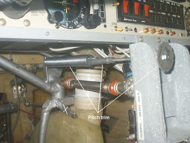 11/12/04: Post build note:
Trim control revision. I had bad luck with purchased trim systems. Originally I installed Ran's trim control - typical wheel type - with plastic gears which proved not sturdy enough in flight because of the extra forces required with canard elevator. The second effort was Strong's pitch trim for canards but which did not fit with the yoke assembly.
The left photo shows my $15 pitch trim solution - a spring with a screw jack for the threaded rod with a slightly re-shaped 2" fender washer as an adjusting knob. Not seen is a locknut about 3" on the threaded rod in front of the washer that is held against a metal plate on the lower console front vertical part. With a little bit of grease the system seems to work fine. This simple pitch trim could be conceivably used with control sticks too.
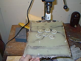 Don't throw away all those scrap glass pieces. I collected them together and
glassed them to about 3/16" and then used them for crush plates floxed inside center console
side plates (replacing the inside foam) to mount various things on.
Don't throw away all those scrap glass pieces. I collected them together and
glassed them to about 3/16" and then used them for crush plates floxed inside center console
side plates (replacing the inside foam) to mount various things on.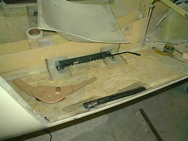 I didn't like the idea of fixed position front seats and adjustable pedals. So I got
Toyota auto seat slider and recliner mechanisms from a salvage yard (the two door model which allows
tilting seat forward - all with one knob - for rear passenger entry).
The sliders and recliners were the most simple and compact I could find in the yard.
The sliders (after a lot of cutting welding) can be seen mounted on the floor here.
The KLS factory was kind enought to give me a second rear seat pan free which I split
into two and will glass/weld into place on top of the seat slides.
With the rounded depressed seat pans I will
get seating fairly close to the floor (I am 6' and need the headroom) AND sliding
seats to boot. However the extra luxury will probably cost me 15 pound weight penalty.
The reclining mechanism is about 3 lbs each, but drilling it full of holes, where
it doesn't compromise strength, could reduce the weight.
I didn't like the idea of fixed position front seats and adjustable pedals. So I got
Toyota auto seat slider and recliner mechanisms from a salvage yard (the two door model which allows
tilting seat forward - all with one knob - for rear passenger entry).
The sliders and recliners were the most simple and compact I could find in the yard.
The sliders (after a lot of cutting welding) can be seen mounted on the floor here.
The KLS factory was kind enought to give me a second rear seat pan free which I split
into two and will glass/weld into place on top of the seat slides.
With the rounded depressed seat pans I will
get seating fairly close to the floor (I am 6' and need the headroom) AND sliding
seats to boot. However the extra luxury will probably cost me 15 pound weight penalty.
The reclining mechanism is about 3 lbs each, but drilling it full of holes, where
it doesn't compromise strength, could reduce the weight.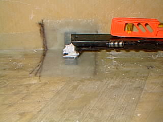 One of the challenges with welding and fiberglass is welding two pieces of
metal which need to be positioned on fiberglass. You can't weld it while it is
on the cured fibreglass. What I did is to position the two metals in place and then
use 5min epoxy/flox mixture to hold the two metals together and then take
them out and weld oposite side to epoxy. The epoxy holds well enough to
get a spot weld to hold the pieces and finish the job. The 5 minute burned epoxy smells
like a baking factory, but it crumbles off easily and can be scraped
off with a metal brush. The airframe epoxy I use (Aeropoxy) does not burn off as easy.
One of the challenges with welding and fiberglass is welding two pieces of
metal which need to be positioned on fiberglass. You can't weld it while it is
on the cured fibreglass. What I did is to position the two metals in place and then
use 5min epoxy/flox mixture to hold the two metals together and then take
them out and weld oposite side to epoxy. The epoxy holds well enough to
get a spot weld to hold the pieces and finish the job. The 5 minute burned epoxy smells
like a baking factory, but it crumbles off easily and can be scraped
off with a metal brush. The airframe epoxy I use (Aeropoxy) does not burn off as easy.
Well this project is nearing 700hrs and is far from finishing - still don't
see the light at end of the tunel. Guess some of these extra mods are gobling
up time.
 The instrument panel plate shown mounted. I decided to remove the factory instrument panel
bulkhead and mount a aluminum channel on bottom with modified center console
support as shown. The panel is attached to center console support and bolted to sides
of cabin on glassed supports. The top of the panel plate will be held in place by
the glare shield.The bottom aluminum trim channel gives more rigidity
for pilot or passenger to grab on to when adjusting seat position -
the Cessna 172 trainer reminded me of that with its flimsy panel bottom.
The instrument panel plate shown mounted. I decided to remove the factory instrument panel
bulkhead and mount a aluminum channel on bottom with modified center console
support as shown. The panel is attached to center console support and bolted to sides
of cabin on glassed supports. The top of the panel plate will be held in place by
the glare shield.The bottom aluminum trim channel gives more rigidity
for pilot or passenger to grab on to when adjusting seat position -
the Cessna 172 trainer reminded me of that with its flimsy panel bottom.
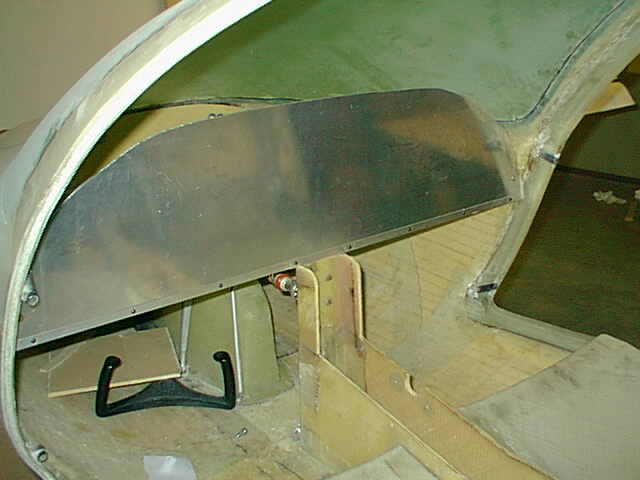
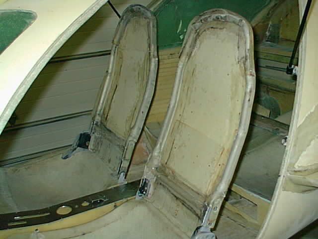
 And finally the right front seat is taking shape. I added / welded aluminum tubing for
additional support - being suspicious that the factory seat pans might not be rigid enough.
(My aluminum welding skill is improving.) The tubing will be partially overlaid with glass
for attachment to back pans. With the seat all the way back its much easier to get
in than with fixed seats. The seat back is mounted higher than factory so that
at 6' even I can rest my head back. And with the rounded depressed seat bottom clearing only
about 1/2" from floor, the headroom is now adequate for me even with the sliding seats. I had to tilt
my head in the factory model and pedals were too close - the factory model was size fitted
for Stan, the KLS manager, who is shorter than me. There is now no real need to adjust pedals in
this unit but instead of cutting the pedal stems off, I shortened them down to 3 adjustment
holes for ergonomic fine tuning.
And finally the right front seat is taking shape. I added / welded aluminum tubing for
additional support - being suspicious that the factory seat pans might not be rigid enough.
(My aluminum welding skill is improving.) The tubing will be partially overlaid with glass
for attachment to back pans. With the seat all the way back its much easier to get
in than with fixed seats. The seat back is mounted higher than factory so that
at 6' even I can rest my head back. And with the rounded depressed seat bottom clearing only
about 1/2" from floor, the headroom is now adequate for me even with the sliding seats. I had to tilt
my head in the factory model and pedals were too close - the factory model was size fitted
for Stan, the KLS manager, who is shorter than me. There is now no real need to adjust pedals in
this unit but instead of cutting the pedal stems off, I shortened them down to 3 adjustment
holes for ergonomic fine tuning. 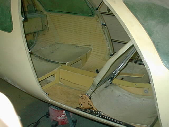 With the seats all the way front and tilted forward there is a lot more room for entry into
rear.
With the seats all the way front and tilted forward there is a lot more room for entry into
rear.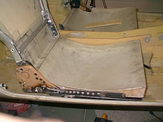 As can be seen, the recliner mechanism was cut down to shortest size without affecting
its operation. The extra holes are an attempt to reduce weight. The recliner mechanism
is welded to top part of the free slider to which the seat is bolted to with two 1/4"
bolts. The aluminum frame
is bolted to steel plates - one on the recliner mechanism side and the other side
which has a simple 5/16 bolt for a pivot.
As can be seen, the recliner mechanism was cut down to shortest size without affecting
its operation. The extra holes are an attempt to reduce weight. The recliner mechanism
is welded to top part of the free slider to which the seat is bolted to with two 1/4"
bolts. The aluminum frame
is bolted to steel plates - one on the recliner mechanism side and the other side
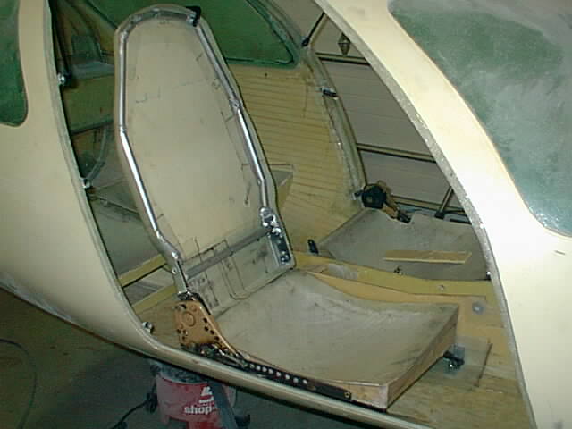
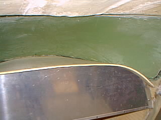
which has a simple 5/16 bolt for a pivot.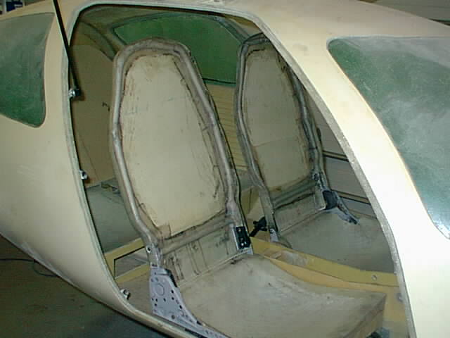 And now both seatbacks installed - showing rear seat seatback plates in place too.
The front seatback aluminum frames were overlaid with 2 ply S glass which really
gave rigidity to the seats.
And now both seatbacks installed - showing rear seat seatback plates in place too.
The front seatback aluminum frames were overlaid with 2 ply S glass which really
gave rigidity to the seats.
Now that's what I call bucket seats.
 Rear seats are fixed in place with seatbacks (piano) hinged to fold forward for
access to space behind. Two front seat belt anchor plates can be seen with holes for
bolts - covered with about 10 plies of S glass. The far anchor shows the rudder
cable tubing covered in place with the plies (arrow) - the tubing should be placed
before rear seats are glassed into position.
Rear seats are fixed in place with seatbacks (piano) hinged to fold forward for
access to space behind. Two front seat belt anchor plates can be seen with holes for
bolts - covered with about 10 plies of S glass. The far anchor shows the rudder
cable tubing covered in place with the plies (arrow) - the tubing should be placed
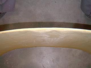
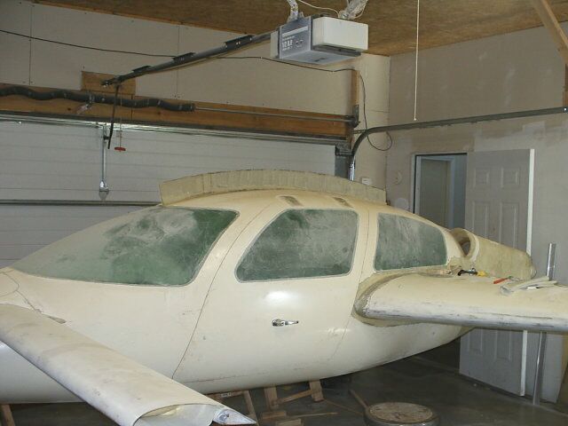
before rear seats are glassed into position.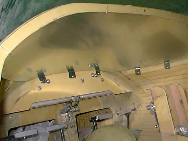 Glare Shield.
It is kind of awkward
to make since it needs a smooth transition contour from instrument
panel to front of windshield. I decided the easiest way was to place a
24 gauge sheet metal mold fastened over the instrument bulkhead piece
(that I had taken out before) and mount the sheet metal where the
glare shield will go - about 3/8" lower forward to allow for thickness
of glare shield. It is held down on top of the bulkhead piece curve by
few pieces of thin wire. The sides of the metal sheet are held in
place by several tabs I left out in the metal when cutting it and
these are screwed into position to the fuselage sides.
The sheet metal side curves were cut from a cardboard pattern.
The sheet metal really makes a smooth transition surface.
Hmmm... engine cowl mould?
Glare Shield.
It is kind of awkward
to make since it needs a smooth transition contour from instrument
panel to front of windshield. I decided the easiest way was to place a
24 gauge sheet metal mold fastened over the instrument bulkhead piece
(that I had taken out before) and mount the sheet metal where the
glare shield will go - about 3/8" lower forward to allow for thickness
of glare shield. It is held down on top of the bulkhead piece curve by
few pieces of thin wire. The sides of the metal sheet are held in
place by several tabs I left out in the metal when cutting it and
these are screwed into position to the fuselage sides.
The sheet metal side curves were cut from a cardboard pattern.
The sheet metal really makes a smooth transition surface.
Hmmm... engine cowl mould?
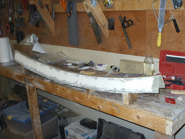
A low density 1/4 foam sandwiched between two glass plies ought to do
it - in two steps. First step is to glass the bottom side of the foam,
cover with peel ply and plastic sheet (keep it from sticking to the
sheet metal) and then simply slide it in over the sheet metal to cure.
The top layer should then go on the curved surface held by the bottom
layer. The glare shield will stick out a few inches back over the panel.
 Since I used an extra pair of "rear" seat pans for the front, and they do not have
leg rests like the factory arangement, I glassed about 2" of curved seat extension to the front
using two layers of 2200 BID spare glass.
Since I used an extra pair of "rear" seat pans for the front, and they do not have
leg rests like the factory arangement, I glassed about 2" of curved seat extension to the front
using two layers of 2200 BID spare glass.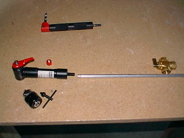 Fuel tank selection control: one awkward aspect of
canards & pushers is fuel selection handle placement. One way is to
place the valve in center console and then route the fuel lines to it
and then back. That crowds the center console as well as having a more
difficult plumbing problem. I decided to place the handle in center
console and fuel valve in the back where the fuel lines come in from
the side strake tanks and use a 90 degree control offset connected to
a torque tube and then to the valve. I got the idea of using a angle
drill adaptor and initially purchased an adapter (about $50) from
Lock-N-Stich. It was made of plastic and was lightweight. But the
plastic gears and bushing bearings and the screw in only drill bits
receptacle did not impress me. I later found an adapter with a a 3/8
chuck for about $15 from
Harbor Freight Tools (item number 43623)
and decided to take a chance. It arrived this weekend (5/12/02) and
turned to be surprisingly sturdy quality - all metal, 3 ball bearings,
1 needle bearing and easy to atach knob and tail end connections -
although about 5 ounces heavier. As shown the chuck end has a 3/8
thread and a keyway behind it, perfect for adapting a small handle
which I fabricated out of two layers of metal - one for the lower
keyway (drilling/filing to shape) and the other for the top hole which
were then welded together and a handle extension was welded on top
(painted red along with the fastening nut). The selection valve is
from McMaster-Carr (about $25, part No 46095K62) which seems to
operate freely without binding. In my setup I will probably need only
1 u-joint between the adapter and valve, and 3/8 tubing connecting the
pieces.
Fuel tank selection control: one awkward aspect of
canards & pushers is fuel selection handle placement. One way is to
place the valve in center console and then route the fuel lines to it
and then back. That crowds the center console as well as having a more
difficult plumbing problem. I decided to place the handle in center
console and fuel valve in the back where the fuel lines come in from
the side strake tanks and use a 90 degree control offset connected to
a torque tube and then to the valve. I got the idea of using a angle
drill adaptor and initially purchased an adapter (about $50) from
Lock-N-Stich. It was made of plastic and was lightweight. But the
plastic gears and bushing bearings and the screw in only drill bits
receptacle did not impress me. I later found an adapter with a a 3/8
chuck for about $15 from
Harbor Freight Tools (item number 43623)
and decided to take a chance. It arrived this weekend (5/12/02) and
turned to be surprisingly sturdy quality - all metal, 3 ball bearings,
1 needle bearing and easy to atach knob and tail end connections -
although about 5 ounces heavier. As shown the chuck end has a 3/8
thread and a keyway behind it, perfect for adapting a small handle
which I fabricated out of two layers of metal - one for the lower
keyway (drilling/filing to shape) and the other for the top hole which
were then welded together and a handle extension was welded on top
(painted red along with the fastening nut). The selection valve is
from McMaster-Carr (about $25, part No 46095K62) which seems to
operate freely without binding. In my setup I will probably need only
1 u-joint between the adapter and valve, and 3/8 tubing connecting the
pieces.
May 2004 afterthought: After getting the factory training in May 2004
I realized that the factory model had individual left and right fuel
shutoff valves rather than the left OR right setup I have. The factory
setup is less work flying since you can just leave both tanks on and
not bother unless there is an imbalance. Did not realize that and put
the left/right valve on because that is the way most are installed.
Thats probably a mod I will do in future (post build).
 After checking that there was sufficient room for avionics, the
instrument panel was shortened - bottom raised by 1" - to make more
easier entry for my 6' frame. The yoke sleeves are shown installed now
and yokes in place - but often I will remove such things to work on
other items.
After checking that there was sufficient room for avionics, the
instrument panel was shortened - bottom raised by 1" - to make more
easier entry for my 6' frame. The yoke sleeves are shown installed now
and yokes in place - but often I will remove such things to work on
other items. The center console is taking shape - trim tab, fuel gauge with L/R
switch and fuel selector handle connected to the 90 degree adapter
which connects to rear fuel valve.
The center console is taking shape - trim tab, fuel gauge with L/R
switch and fuel selector handle connected to the 90 degree adapter
which connects to rear fuel valve.The small handle on front is for an emergency hudraulics release valve which will release the pressure in the landing gear intending it to lower itself into landing position should the electric hydraulic pump fail - will need testing yet, but I added springs aiding the lowering of landing gear both to front and main gear mechanism. The landing gear is held in retracted position by hydraulic pressure.
Post construction fuel level gauge notes: The initial gauges/senders were Skysports dual senders, single gauge with a switch. It is a low voltage system which is difficult to calibrate. During FAA inspection, the inspector pointed out that one aircraft accident was caused by confusion with the switch/tank selection. After inspection I decided to convert to dual fuel gauge. After bad advice from Westach I purchased the wrong gauge (5V system dual fuel gauge). After wrecking that one I had to purchase the correct dual gauge from Skysports. But it turned out again difficult to adjust, and the senders went kaput from the fuel and water leaking on top. Then I tried using less expensive resistive senders that match that gauge, but there was no room in the tank holes or position to install them. Eventually, 06/04/04, I purchased a new Westach 5V dual fuel gauge, dual capacitive sender system which worked. A hint is to dab the sender screws on bottom thread and head tops with "Aviation Form-A-Gasket" goo so that fuel will not rise up the threads and affect the sender tops - and also seal the sender housing covers with silicone to keep weather out. The whole thing cost me about twice the price of the correct system I should have got in the first place. Sometimes trying to save money turns into wasting it. Oh the joys of building.....
 Since I am placing more of avionics and controls along the top of
center console I found the factory width seat backs interfered with my
elbow motion. This shows the seat backs width narrowed down by 2.5" to
allow safer arm motion to reach controls along the centre and still
leaves plenty of back support. This is one of those not easily
predictable results - chalk up another extra 8 hours of work.
Since I am placing more of avionics and controls along the top of
center console I found the factory width seat backs interfered with my
elbow motion. This shows the seat backs width narrowed down by 2.5" to
allow safer arm motion to reach controls along the centre and still
leaves plenty of back support. This is one of those not easily
predictable results - chalk up another extra 8 hours of work.The fabricated lid is losely placed to show connection positions with switch and went on top and fuel outlet connection, foreground left. I wanted more fuel in the tank but the seat belt and seat back hinge mountings prevented it so I decided to add a top hump to the tank increasing the volume by another .5 gallons. That should give me a 2.25 gallon warning in case of fuel runout or if I forget to switch tanks.

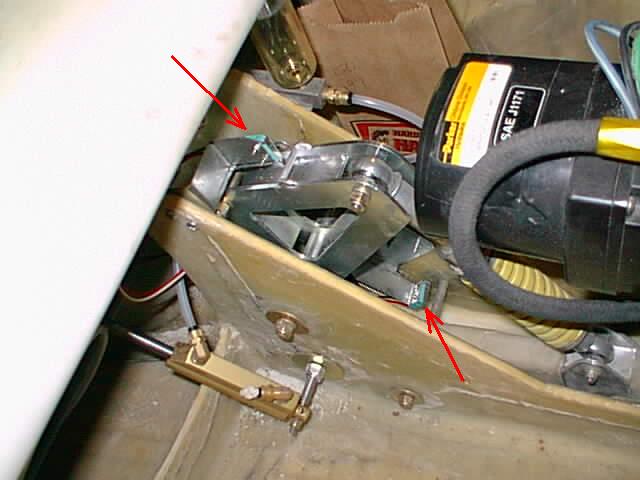 Showing the upper and lower front gear up/down indicator micro
switches.
Showing the upper and lower front gear up/down indicator micro
switches.
This is the point where I am bogged down in figuring out a lot of
interelated details. The upper LS strake cannot be closed until the RG
indicator switches are in place. I have to make sure I have all the
necessary holes/wires/whatever before closing the strake top or it may
be quite difficult access with the strake top permanently in
position.
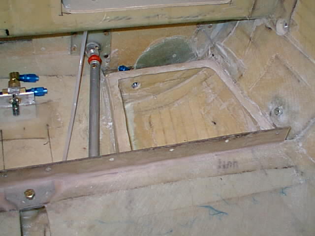
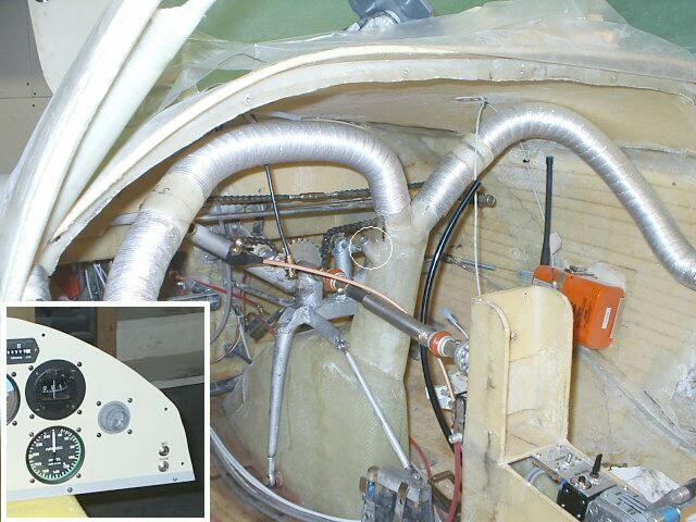
 The sump tank vent joins up with LS tank vent and leads to the outside
of firewall using a fabricated aluminum block I made. Fuel inlet line
is shown leading from fuel valve undreneath aileron torque tube and to
behind of sump tank. Some RG hydraulic connection work is seen inside
the spar.
The sump tank vent joins up with LS tank vent and leads to the outside
of firewall using a fabricated aluminum block I made. Fuel inlet line
is shown leading from fuel valve undreneath aileron torque tube and to
behind of sump tank. Some RG hydraulic connection work is seen inside
the spar. The up/down control and position indicator circuit was made from 3
double color LED's - one for each gear - and a momentary toggle switch
to turn on the circuit relays that activates the hydraulic pump. A
simplified circuit block diagram is shown.
The up/down control and position indicator circuit was made from 3
double color LED's - one for each gear - and a momentary toggle switch
to turn on the circuit relays that activates the hydraulic pump. A
simplified circuit block diagram is shown.
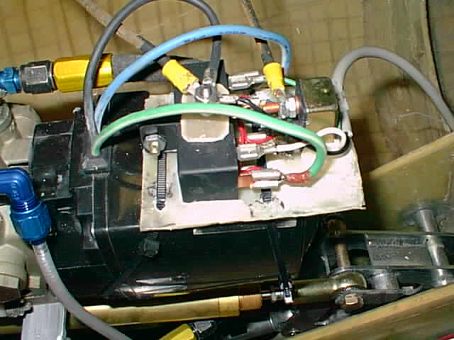 The pump relay & 50A thermal auto fuse circuit shown straped to pump.
The auto fuse resets itself automatically after 15s and is avialable
from auto stores. The mounting pad was simply made from a little bit
of glass/epoxy - another handy feature of fibreglassing is that you
can fabricate different shapes for many different purposes.
The pump relay & 50A thermal auto fuse circuit shown straped to pump.
The auto fuse resets itself automatically after 15s and is avialable
from auto stores. The mounting pad was simply made from a little bit
of glass/epoxy - another handy feature of fibreglassing is that you
can fabricate different shapes for many different purposes.
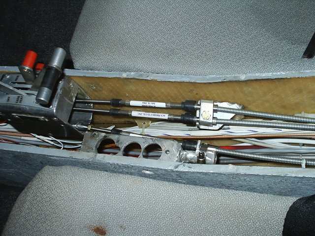
There just was not enough room in the ACS type quadrant to fit in terminals or bug nuts (which I did not trust). So I welded my own terminals using strips of steel and 3/16 short bolt and nut. A wire grip (from A.Spruce or Wicks) is then welded to the end of the strip.

9/26/04 Post build note: The above cables type did not hold up in flight
and started binding. Had to replace all 3 cables with type A920 control cables.
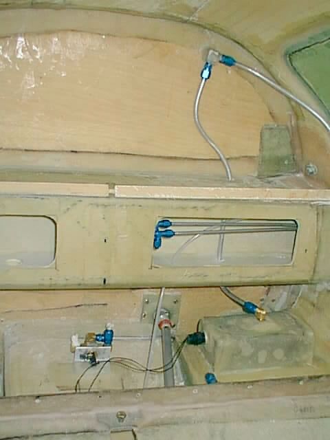
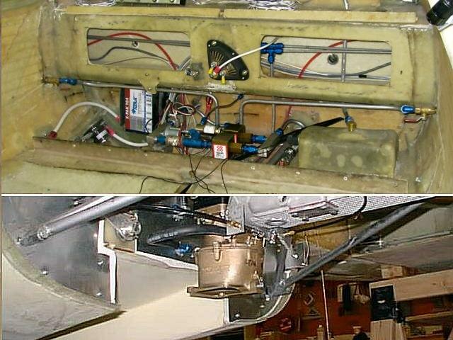 There were some recent AD's on the Franklin mechanical fuel pump and
the pumps were hard to get. And for cost reason I decided to go with
double Facet electric pumps (with double independent batteries). The
small size makes the whole fuel system fit behind the back seat.
There were some recent AD's on the Franklin mechanical fuel pump and
the pumps were hard to get. And for cost reason I decided to go with
double Facet electric pumps (with double independent batteries). The
small size makes the whole fuel system fit behind the back seat. With this arrangement the engine compartment has only a short fuel hose from the firewall to the carburetor. This minimizes fuel vapor problems from engine heat and possible fuel fire problems. I feel this is a better overall risk even with the undesirable fuel plumbing inside cockpit. The system inside includes the filter, two electric fuel pumps, two check valves, fuel pressure and fuel flow sensor.
 03/23/2010 more detailed carb photos:
I recently purchased a Rotec TBI
and will try to install and test it this summer.
Will be selling the Franklin MA-5 carburetor. It only has 200 hours on it since new.
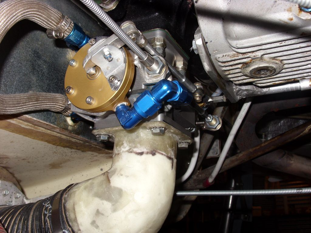
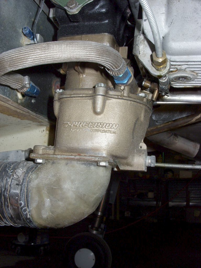
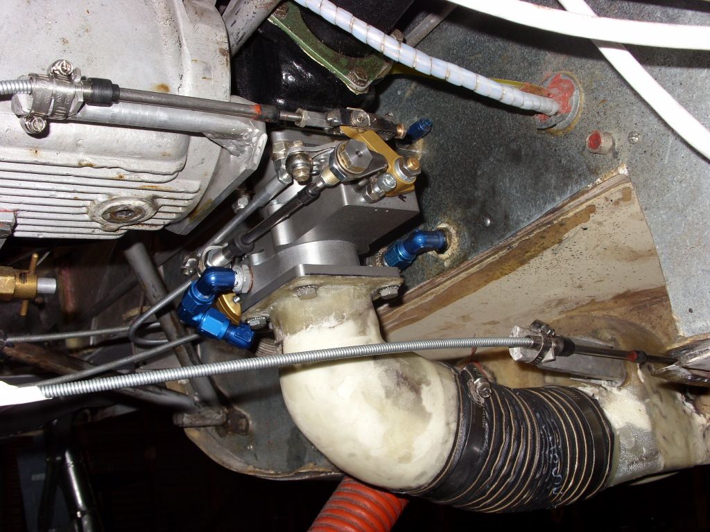 05/26/2010 Rotec TBI installation:
Here is the installation of the Rotec TBI-48-4/5 on my Franklin 6A-350. The TBI sure looks tiny compared to the bulky carb. Notice above how much more the carb stick out below the oil pan.
I tried a static run outside of the hangar and it ran well up to full static RPM. For whatever
reason the engine seemed to run smoother than with the carb.
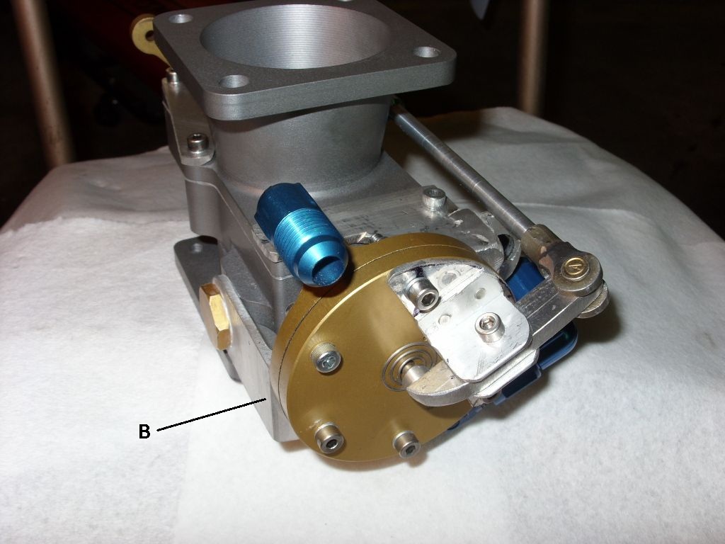
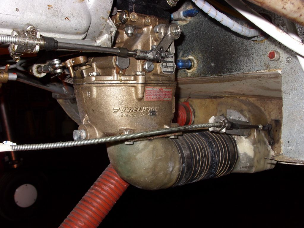
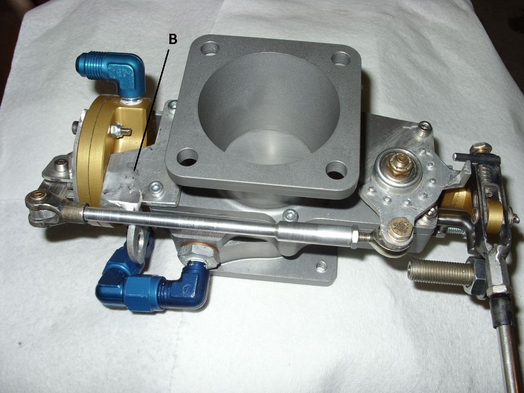 The unique feature on the Rotec model (missing on Ellison) is a primer button on the pressure
regulator. When depressed it releases extra fuel into intake tubes to help with cold starting.
The unique feature on the Rotec model (missing on Ellison) is a primer button on the pressure
regulator. When depressed it releases extra fuel into intake tubes to help with cold starting.
With the aid of a spring / mechanical-slide I implemented a unique linkage that permits the mixture control cable to go beyond the rich mix stop and activate the primer button. That makes it easy to regulate the mixture and prime the cold engine with only one control cable.
You can see extra brackets (B) to hold the pressure regulator to the TBI.
I do not trust AN fittings alone to hold the regulator against engine vibration and control cable force.
05/30/2010 TBI Test Flight
Took the Rotec TBI for an hour+ test flight in mild turbulent air with good results.
Everything worked smooth with no hesitation or unexpected responses.
I have not checked out WOT top end yet, but takeoff WOT gave 2400 RPM the same as the carb.
There are two noticeable advantages.
1. Smooth leaning with less fuel consumption (from about 6.5gph down to about 6gph at 135kts). That is good for a 2250-lbs gross aircraft.
2. No significant hesitation when changing throttle at lean setting.
A few surprises were 1. that the throttle lever requires noticeable more force since the slide throttle has more friction. 2. Turning on carb heat seems to have less effect on engine RPM. 3. The TBI did not cutoff when fuel pumps were turned off. It keept going - assumedly sucking the fuel out of the lines somehow.
06/02/2010 TBI Test Flight
Went up for a short cruise. Only two things to report.
1. I tried leaning on the takeoff climb and the engine cut out. It took a few seconds to restore the rich mix and adjust
the throttle to resume power.
2. While in cruise I turned off both Facet fuel pumps and the TBI kept working. Without fuel pump pressure it requires slightly more rich mix.
The fuel tanks are about 30 cm above the TBI.
Guess it sucks the fuel through the two parallel electric Facet fuel pumps.
That is good news in case both fuel pumps fail. The carburetor would
not run without fuel pump pressure.
06/03/2010 TBI hangar note:
Went to the hangar to do some work. Noticed puddle below the carb. Fuel was dripping slowly from the carb throat.
Either the pressure control does not hold the static fuel or some dirt is in the line - I have inline filters and do not expect it.
Fortunately I have an emergency shutoff valve before the fuel pumps and that seems to stop the drip. Guess I will have to shut
the valve everytime I finish flight and turn it on before flight.
06/04/2010 TBI flight:
Another 0.8 hour flight. No surprises. I made sure to turn off the fuel shutoff valve after flight to avoid fuel dripping.
This is probably the last TBI report unless I find something else unique about it.
06/07/2010 TBI hangar note:
Forgot to shut the fuel line the day before after another flight. But found no fuel puddle or dripping. Did notice a fuel smell.
07/18/2010+ TBI flight problems:
I traded in my carburetor for a set
of new forged 8.5 compression pistons in anticipation of eventual shortage of
100LL and possibly burning 92 octane autogas. I installed the pistons and tried
fast taxi runs. The engine run at lower rpm but stumbled and lost power at WOT.
Tried a mod suggested by Rotec which didn't work. This made me miss flying to
OSH this year - but went by car.
10/08/2010 Problem resolved:
This queer problem kept me grounded for three months.
Tried everything I could think of: decreasing the gap between pressure regulator diaphram and the valve with JB weld (as per Rotec suggestion), changing the TBI pressure regulator springs (spent $200+ on various special tiny springs), Rotec 2010 Sep 2 TBI AD mod, new set of plug wires, replacing fuel and air filter, and other things. Then it popped into my head to remove the Franklin manifold equalizer tube and plug the manifold end holes. And it worked - rock steady throttle response. A couple days before I was ready to purchase a rebuilt carburetor - $1700 - but fortunately the supplier did not have stock.
It seems the problem is that with the lower compression pistons at higher air flow, the extra air volume in the tube set up some sort of manifold pressure variations and would destabilize the TBI which requires constant pressure drop at the nozzles.
I talked to the Franklin guy who sold me the 8.5 pistons and he did not seem to believe me - never heard of anything like it. But of course he dealt with carbs and not TBIs.
![]() Click left to see the photo of closing up the manifold tube ends -
a rubber stopper and a hose to hold it securely to the manifold. On the other side
a good idea is to wrap an insulating shield around the same thing to protect its
proximity to the exhaust manifold.
Click left to see the photo of closing up the manifold tube ends -
a rubber stopper and a hose to hold it securely to the manifold. On the other side
a good idea is to wrap an insulating shield around the same thing to protect its
proximity to the exhaust manifold.
10/13/2010 Flight test:
After sorting out some other problems - shimmering brake rotors - I took it up for about an hour.
It was difficult
to tell difference between the 10.5 and 8.5 pistons. The static rpm and the climb rate
are nearly identical. And I can use 92 octane autogas. Theoretically
there should be a 6 percent power loss when changing from 10.5 to 8.5. The
difference should show up at altitude where higher compression is usually an
advantage.
NOTES:
The Rotec TBI "equalization tube" mod to make it more like Ellison did not help in my case.
I tried the "mod" before they sent out the
AD. I tried designing an airbox to improve even flow into the TBI but that did not help performance.
In fact the original air intake tube shown above with the ram air effect gave me about 40 rpm more
at take off. The airgrid sold by Aircraft Spruce also adds about 20 rpm.
The fuel flow amount in my case depends how far up the intake tube I put the small connector tube. Just near the throat is too lean and will stall on WOT takeoff. Further up the intake tube it is too rich and I get a lot of soot on exhaust pipes. The intake has good underbelly air ram effect which changes the pressure gradient from normal TBI installations. For now I just left the mod "balance" hose disconnected.
TBI Conclusions:
With some adjustment you can get the TBI working - airbox design, "equalizer
tube" positioning, etc. to get optimal performance. The
CARB
AIR GRID available from Aircraft Spruce adds a bit to performance.
You may have a lot of "fun" installing and testing a TBI. The TBI installation is not straightforward like a carburetor.
Since Franklin carbs are difficult to get, Rotec TBI is a viable replacement for Franklin powered experimentals.
06/06/2011 Update: I still had issues with the 8.5 pistons and TBI combo that
I could not resolve in reasonable time and expenses and
decided to replace the Franklin with a complete rebuilt TCM IO-360-C with
new accessories which I got for $8k.
07/12/2012 Note: One of those issues was rich carbon deposits on plugs and piston
which tended to cut power down as I flew.
Turns out I had the same problem with the new TCM IO-360 - probably caused by too cold heat
range plugs used in both cases.
I used the same plug for 8.5 pistons from the 10.5 pistons. Lower compression pistons
require hotter range plugs (careful - not too hot or it may cause detonation). That
was something I was not aware of.
12/18/2011As of this date I sold the TBI and parted out most of Franklin parts for $6300 which helped to recover good portion of the TCM IO-360-C purchase cost. That may improve since I still have some parts to go.
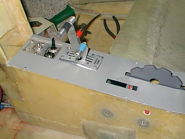 The center controls are taking shape. Had to enlarge the RG control
mounting plate to include IVO electric prop control switch and
breaker. The ACS type quadrant came with a large gap around the
levers. I fabricated a cover plate using an aluminum plate and a
rotary tool. The ACS type quadrant has a main square shaped bolt
holding the throttle levers in place. If end nut (red friction
adjustment) should come of the main bolt could work itself off into
the center console resulting in loss of control. I riveted a small
plate (under center console cover - not seen) on the outside against
the square bolt on left side so that at least it stays in place.
The center controls are taking shape. Had to enlarge the RG control
mounting plate to include IVO electric prop control switch and
breaker. The ACS type quadrant came with a large gap around the
levers. I fabricated a cover plate using an aluminum plate and a
rotary tool. The ACS type quadrant has a main square shaped bolt
holding the throttle levers in place. If end nut (red friction
adjustment) should come of the main bolt could work itself off into
the center console resulting in loss of control. I riveted a small
plate (under center console cover - not seen) on the outside against
the square bolt on left side so that at least it stays in place. 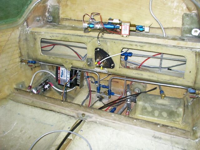 The wiring and plumbing inside is getting messier. I decided to place
both batteries inside fuselage - one on front and one behind rear
seats - and most of wiring, fuel pumps and electrical controls, behind
rear seats. This will eliminate a lot of engine heat problems on
controls and fuel systems. There is only about 1 ft of fuel hose in
engine compartment to carb. Having these items inside fuselage and the
fact that Franklin accessories (starter, alternator, etc) are on the
front (rather than aft as with a IO-360 lycoming) should improve
weight & balance.
The wiring and plumbing inside is getting messier. I decided to place
both batteries inside fuselage - one on front and one behind rear
seats - and most of wiring, fuel pumps and electrical controls, behind
rear seats. This will eliminate a lot of engine heat problems on
controls and fuel systems. There is only about 1 ft of fuel hose in
engine compartment to carb. Having these items inside fuselage and the
fact that Franklin accessories (starter, alternator, etc) are on the
front (rather than aft as with a IO-360 lycoming) should improve
weight & balance. 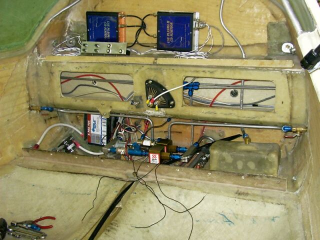 And messier - especially when things have to be changed. Wish somebody
done all this before and shown it on the web for me to see. Turns out
some of these changes are costing considerable extra money/time -
finding out that they do not work first time and have to be
rearanged.
And messier - especially when things have to be changed. Wish somebody
done all this before and shown it on the web for me to see. Turns out
some of these changes are costing considerable extra money/time -
finding out that they do not work first time and have to be
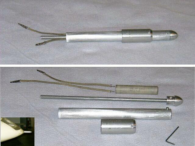
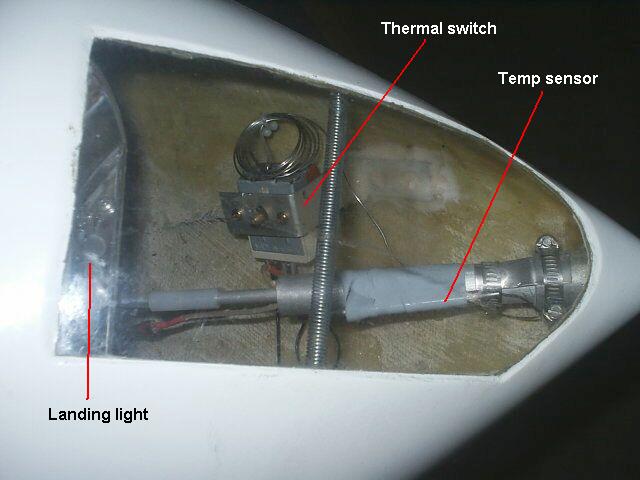
rearanged.The heated pitot tube is made up of 80W 12V Cessna pitot tube heater (part No. 0721105-5) which I got from KRN Aviation It fits inside a 3/4 od, .0620 wall alum tubing - reamed to 5/8 id for the length to slide the heater to right position from outside. with a .25 x .035 wall inside tube. The outside 1 od, 3/4 id fat tube piece holds the whole assemby with a set screw and is glassed in the nosecone. Everything else comes appart for replacement. Again, the small lathe was handy in fabricating the rounded nose with the stepped diameters.
For non IFR a suggested pitot tube is a large diameter opening (about 3/4 OD) and then a small 1/4 takeoff from top rear of tube. This was done by a EZ builder to make an "icing resistant" pitot tube. The idea being that it would take a lot of icing before the big tube gets plugged up. And because of the large surface it is possible that the large tubing could pickup heat from inside cabin and melt icing.
11/04/04 Post build notes:
The pitot tube when turned on gets awfully hot. I decided to install a
temperature control. Got a thermal automotive fan switch
(JCWhitney.com part ZX378602B). After installing I found it did not
stop the heater and realized it is a temperature "ON" switch with temp
increase. So I got a SPDT automotive 30A relay (PartsExpress.com part
330-077) to reverse to off with temp increase.
09/2006? Post build note:
I replaced both the relay and the thermal switch with a simple
home water heater thermostat available at local hardware stores.
A simpler way and saved an ounce of weight.
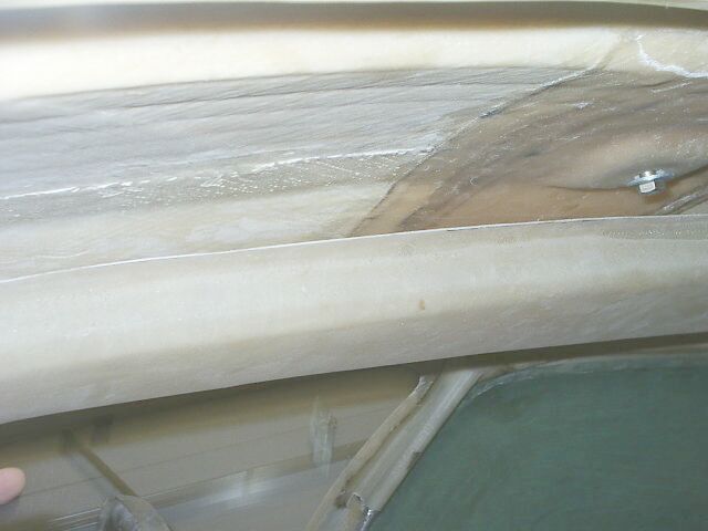
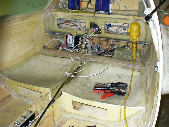 The wiring is more messier. Takes long time to do it carefully -
strain relief, good electrical connections, etc. In many cases I did
not trust the crimping connections, even though I have a pro crimper,
and resolved to soldier the terminal in addition to crimping.
The wiring is more messier. Takes long time to do it carefully -
strain relief, good electrical connections, etc. In many cases I did
not trust the crimping connections, even though I have a pro crimper,
and resolved to soldier the terminal in addition to crimping.The idea was to use the through to conduct hot/cold air from the fan (white unit shown at back) to the front and install lights and vents inside the through. But then I changed my mind and simply left the whole thing open to the fan as is (maybe will paint the fan).
At the front is shown the small console for the LED lights (map light, and 2 instrument panel lights) and the rear fan switch. I formed the console from aluminum sheet. The wiring to the console is shown embedded in the ceiling.
The 12V lamp like LED's are available from Digi-Key Electronics, part number: 441-1008-ND.
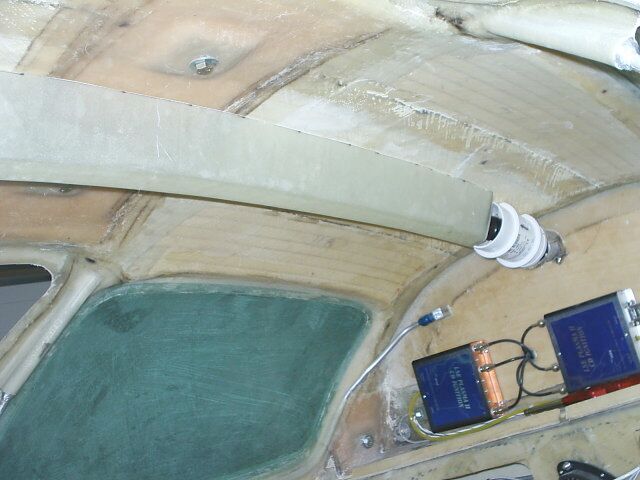
 This unique takeoff on the front RG wheel well is my attempt at
ventilation. There is this big hole underside anyway which collects the higher
pressure air. Sure saves gouging two side vent holes for NACA scoops and adding
more drag.
The ducting goes to the the two front panel vent controls. The small
takeoff is a 5/8 dia alum tubing hole that is used to pipe air to the
Garmin GPS/com XL300 cooling port hole. It seems to get hotter the
most. The high pillar duct is to get over the yoke control
rods and can be plugged up from underside in winter time.
This unique takeoff on the front RG wheel well is my attempt at
ventilation. There is this big hole underside anyway which collects the higher
pressure air. Sure saves gouging two side vent holes for NACA scoops and adding
more drag.
The ducting goes to the the two front panel vent controls. The small
takeoff is a 5/8 dia alum tubing hole that is used to pipe air to the
Garmin GPS/com XL300 cooling port hole. It seems to get hotter the
most. The high pillar duct is to get over the yoke control
rods and can be plugged up from underside in winter time.07/20/05 Post build test note: These wents work well. In addition I installed a 3" plastic marine inline blower into the pillar for circulation while the plane is taxiing or standing. The duct tubes are aluminum from automotive shops. CAT tubing has steel wire coil which may induce more magnetic effects on the compass and other magnetic field dependent avionics. Now I have two forced fans. Probably will use the rear fan only for warm air heating from engine.
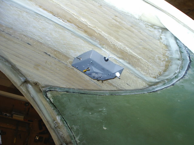
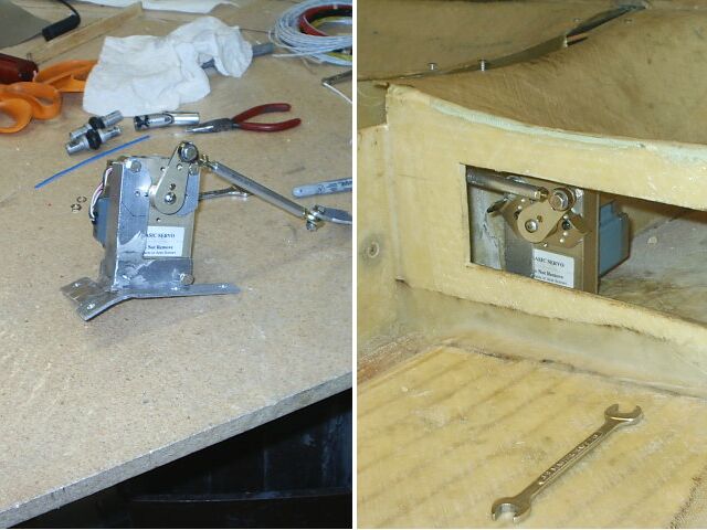 Installing the Digitrak autopilot: The worst part is installing the
2.25 lb servo. This one of the many unique aluminum brackets I had to
fab to mount things. My aluminum welding skills are not all that bad.
I wished to have mounted the 2+ lbs up front to the sliding spline
shaft going to the yokes to improve the balance but decided it was
just not sturdy enough. I finally decided to mount it under the rear
left seat where it is connected with a tie rod to the aileron torque
tube in the center console tunnel. At least that is just ahead of CG.
The worst place would be somewhere near wings to add to the already
heavier engine. (Note: My Franklin 6 is the original US Franklin and
has heavier cylinders - good for durability but adds more weight). The
base of the mounting bracket it floxed/glassed to the floor shape.
Installing the Digitrak autopilot: The worst part is installing the
2.25 lb servo. This one of the many unique aluminum brackets I had to
fab to mount things. My aluminum welding skills are not all that bad.
I wished to have mounted the 2+ lbs up front to the sliding spline
shaft going to the yokes to improve the balance but decided it was
just not sturdy enough. I finally decided to mount it under the rear
left seat where it is connected with a tie rod to the aileron torque
tube in the center console tunnel. At least that is just ahead of CG.
The worst place would be somewhere near wings to add to the already
heavier engine. (Note: My Franklin 6 is the original US Franklin and
has heavier cylinders - good for durability but adds more weight). The
base of the mounting bracket it floxed/glassed to the floor shape.