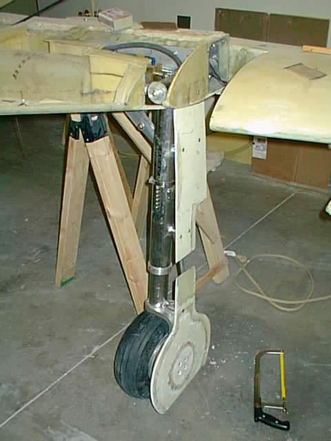
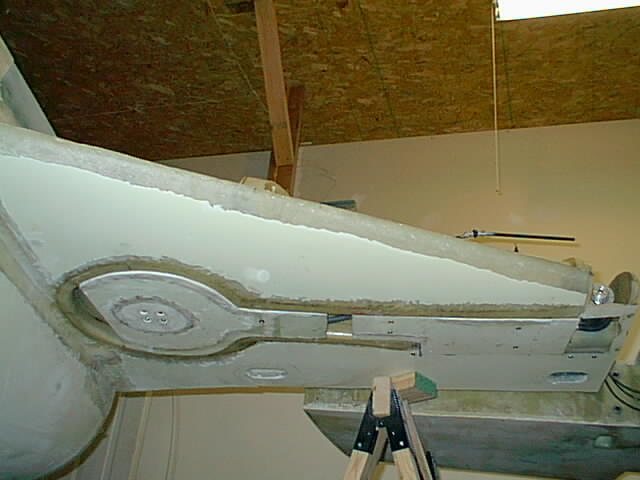
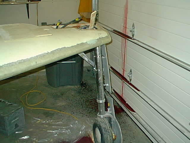
 Showing one of the landing gears. There is an interesting story about the
wheel wells that I got back in August from KLS. I contacted Stan (KLS manager
and designer) asking why the wheel wells are 17" dia and the wheels are only
13" - it takes up more fuel space and asked how I could reduce it. He indicated
that it was to tire manufacturer varying wheel size diameters and builder slopines.
Then I havent heard from him on that. But last Monday (11-26-01) a parcel arrived
at the post office with two more wheel wells of reduced diameter (14.5"). Both
wheel wells are shown here indicating the size reduction. That was nice of KLS
- showing they are trying to please. If the smaller wheel wells work out
it would mean about 5 gallons extra fuel.
Showing one of the landing gears. There is an interesting story about the
wheel wells that I got back in August from KLS. I contacted Stan (KLS manager
and designer) asking why the wheel wells are 17" dia and the wheels are only
13" - it takes up more fuel space and asked how I could reduce it. He indicated
that it was to tire manufacturer varying wheel size diameters and builder slopines.
Then I havent heard from him on that. But last Monday (11-26-01) a parcel arrived
at the post office with two more wheel wells of reduced diameter (14.5"). Both
wheel wells are shown here indicating the size reduction. That was nice of KLS
- showing they are trying to please. If the smaller wheel wells work out
it would mean about 5 gallons extra fuel.
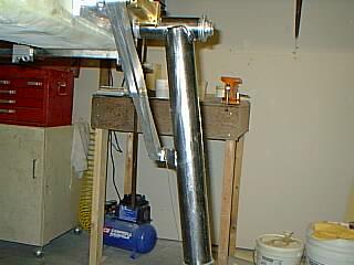
 Attempting to compress the RG strut.
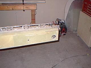
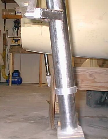
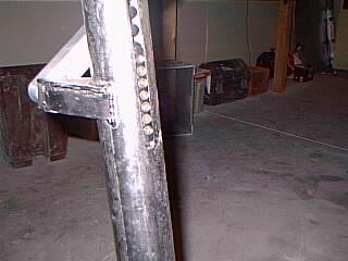
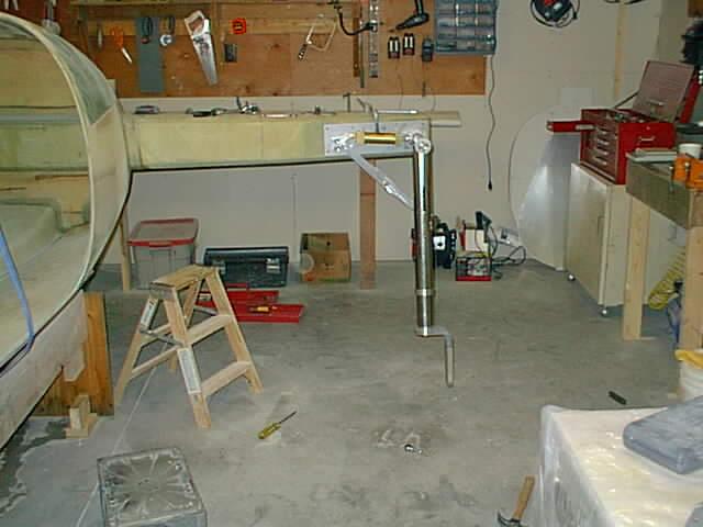 Showing the LH strut clamped in position. By hand rotation I found that
the RH strut scissor mechanism was binding. The trunion
pin angle was too large (7 degrees instead of designed 5.5). After a few
emails, the factory promptly sent two new trunion plates. I used only
the RH one since the old LH worked OK with some washer adjustments.
Showing the LH strut clamped in position. By hand rotation I found that
the RH strut scissor mechanism was binding. The trunion
pin angle was too large (7 degrees instead of designed 5.5). After a few
emails, the factory promptly sent two new trunion plates. I used only
the RH one since the old LH worked OK with some washer adjustments.
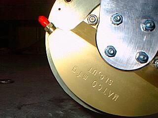 The brake caliper bolt mount did not fit off the fork sufficiently so that a small
notch had to be sanded in the fork to free the sliding motion of the brake caliper.
The brake caliper bolt mount did not fit off the fork sufficiently so that a small
notch had to be sanded in the fork to free the sliding motion of the brake caliper.
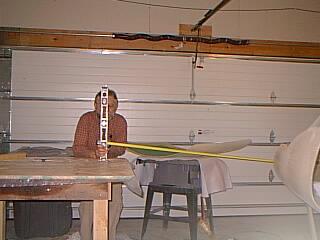
 The factory instructions were a bit vague about wheel toe-in lineup.
I clamped a straight edge on each fork (after mounting the wheels otherwise
would be harder to hold the fork in position while drilling). A chalk line was
made on the garage floor below the center line of the fuselage (use plumb bob).
And two more parallel (equidistant) lines were made on the floor near the
wheels so that I could sight the parallax of the straight edge and the floor
lines to line up the wheels. The center line below fuselage and the parallel line
near right wheel are shown in the photo drawn with MS paint.
The factory instructions were a bit vague about wheel toe-in lineup.
I clamped a straight edge on each fork (after mounting the wheels otherwise
would be harder to hold the fork in position while drilling). A chalk line was
made on the garage floor below the center line of the fuselage (use plumb bob).
And two more parallel (equidistant) lines were made on the floor near the
wheels so that I could sight the parallax of the straight edge and the floor
lines to line up the wheels. The center line below fuselage and the parallel line
near right wheel are shown in the photo drawn with MS paint.
 Irregardless of my efforts I could not compress the struts as instructed.
So I simply moved the sleeve guide up a screw hole hoping that the weight of
the plane will eventually compress the spring and then I can move
the sleeve guides back to original position.
Irregardless of my efforts I could not compress the struts as instructed.
So I simply moved the sleeve guide up a screw hole hoping that the weight of
the plane will eventually compress the spring and then I can move
the sleeve guides back to original position.
OK. Got the things compressed (04/04/02). It took the plane weight and the force of about 3 tiedown straps
to force sufficient movement for the screws to be where they should be.
A good idea is to tape the screw slider opening with some clear plastic
tape to prevent dust entering during construction. Hmmm... What prevents dust/dirt entry
during normal operation? Will have to look into that.
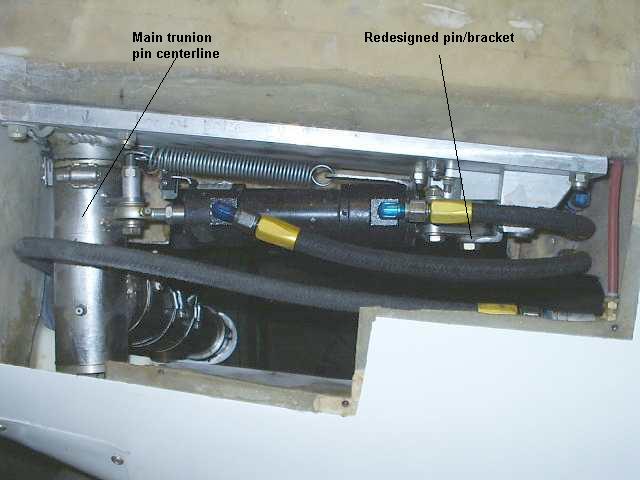
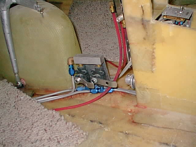
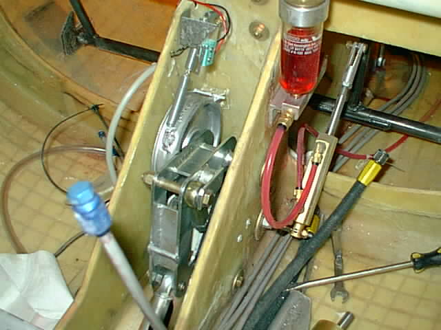
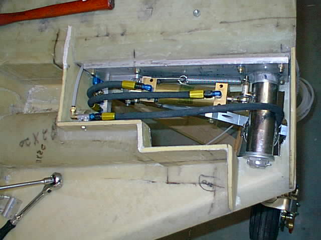 This part has to be done before strakes are closed in. The hydraulic and
brake hose connections needed mounting connection blocks. A simple loose
hose/line connection would chafe and likely fail. The hydraulic connector
block (left) I made out of 1x1 square solid aluminum bar with two
parallel horizontal holes drilled one above the other, top NPT 1/8 holes drilled and
then using alen set screws proper holes were blocked to form two U shaped
conduction channels. Two vertical holes - not interfering with the channels
- were drilled to bolt the block to the strake. (But see 07-01-02 update on
block replacement below due to leakage.) The brake connection block was
made out of a simple pipe welded to a mounting plate to hold in place.
It is important to orient the flex hoses so that they are only in coiling
motion and not torsion - else they may losen up or fail. When gear is down,
the hydraulic hoses should be the shortest length necessary - while the shortest
length for the brake hose is when gear is up.
This part has to be done before strakes are closed in. The hydraulic and
brake hose connections needed mounting connection blocks. A simple loose
hose/line connection would chafe and likely fail. The hydraulic connector
block (left) I made out of 1x1 square solid aluminum bar with two
parallel horizontal holes drilled one above the other, top NPT 1/8 holes drilled and
then using alen set screws proper holes were blocked to form two U shaped
conduction channels. Two vertical holes - not interfering with the channels
- were drilled to bolt the block to the strake. (But see 07-01-02 update on
block replacement below due to leakage.) The brake connection block was
made out of a simple pipe welded to a mounting plate to hold in place.
It is important to orient the flex hoses so that they are only in coiling
motion and not torsion - else they may losen up or fail. When gear is down,
the hydraulic hoses should be the shortest length necessary - while the shortest
length for the brake hose is when gear is up.The spring connected to the LS of cylinder and the RS mounting bolt is my effort to design emergency gear release. Plan to install a hydraulic bypass valve if the electric hydralic pump fails, so that gravity and the spring (which helps to snap the gear into lock position) will help to lower the gear. Another spring will be installed in the nose gear - something else may have to be done too since the NG lowering is against the airstream.
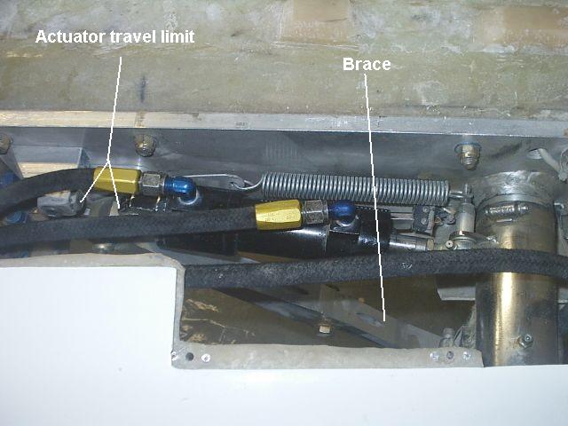 04/23/2004 Post build note:, after FAA inspection. I played around with
the RG and still found the retraction unsatisfactory. It would not retract
with correct force to hold the gear accurately in up position.
The actuator stroke and overall length were too long and the actuator
force and the weight of the RG are "fighting against each other". The photo on
left shows an extra stop block I placed to prevent the back of actuator from
moving further in the up position against the brace top pivot. In the up position
this results in 0 forces on the brace and the only actuator force holding
the gear up, is on the rod end bearing on top of the trunion shaft (right).
Without it there are very high forces on all brace pivot parts and the
rod end bearing - and the weight of the gear is pushing down on the brace
while the back end of the actuator is pushing on top end of the brace.
04/23/2004 Post build note:, after FAA inspection. I played around with
the RG and still found the retraction unsatisfactory. It would not retract
with correct force to hold the gear accurately in up position.
The actuator stroke and overall length were too long and the actuator
force and the weight of the RG are "fighting against each other". The photo on
left shows an extra stop block I placed to prevent the back of actuator from
moving further in the up position against the brace top pivot. In the up position
this results in 0 forces on the brace and the only actuator force holding
the gear up, is on the rod end bearing on top of the trunion shaft (right).
Without it there are very high forces on all brace pivot parts and the
rod end bearing - and the weight of the gear is pushing down on the brace
while the back end of the actuator is pushing on top end of the brace.12/23/2004 Post build note: You may have noticed that the actuator on the left is different from original above. I have replaced all 3 brass "Cylinders & Valves" actuators - two main ones supplied with kit - with steel body actuators from Custom Actuators. The steel ones have a 5000 psi working pressure while the brass ones are 1500psi. Because of that I cranked up the hydraulic force to 1500 psi and reduced the main RG actuators from 1.5" to 1.25" bore. I also saved about 4 lbs weight since the steel actuators are lighter. All this actuator experimenting, and finally getting it right, cost me an extra $800.
 11/30/04 Post build note: After one hard landing(s) I noticed cracks
on the trunion plate bushing welds - both left and right. I had them
re-welded AND welded the aft side of the plate too.
The original weld is quite a small bead and only one side. If
you get the RG from SQ2000 factory, it might be a good idea to weld
a small bead (take it to a good welding shop unless you are a pro) on the
back side and then put an extra heavy bead on top of the front bead already there.
For the back part you will have to bevel the spar hole front where the
trunion bushing goes through to accommodate the new bead.
Not sure if this is a problem with Infinity Aerospace units as well.
11/30/04 Post build note: After one hard landing(s) I noticed cracks
on the trunion plate bushing welds - both left and right. I had them
re-welded AND welded the aft side of the plate too.
The original weld is quite a small bead and only one side. If
you get the RG from SQ2000 factory, it might be a good idea to weld
a small bead (take it to a good welding shop unless you are a pro) on the
back side and then put an extra heavy bead on top of the front bead already there.
For the back part you will have to bevel the spar hole front where the
trunion bushing goes through to accommodate the new bead.
Not sure if this is a problem with Infinity Aerospace units as well.You can see the re-welded job in the post build photo above.

 Showing the brake line connection block with hose and line connected.
The aluminum line to the brake caliper is curved to permit some elastic
yield (Hooke's law) since the caliper is not totally rigid wrt the axle.
Showing the brake line connection block with hose and line connected.
The aluminum line to the brake caliper is curved to permit some elastic
yield (Hooke's law) since the caliper is not totally rigid wrt the axle.

|
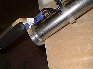
(05/03/2009) Postbuild Note:
I have revised the RG strut connection to the wheel fork. You can see above
that the strut tube is connected to the fork with a single through bolt.
I changed the connection to a slightly adjustable toe settings by enlaring the strut tube bolt hole to oval shape. That way the bolt can be horizontally moved in the oval hole and adjust the toe. I have further added a custom made clamp (welded from 1" high 4130 steel tubing piece) as shown. That eliminates the potential wiggle slop in the strut-tubing/fork-connection with the bolt. Notice the required vertical 1 1/2" slit (front and back) in lower part of the tubing in order to allow the clamp compression. Click photo on left for closer view. A slight toe out is recommended to eliminate gear slop/vibration on ground and emergency gear lowering for touchdown. The 04/13/06 landing gear failure reminded me of touchdown instability with loose landing gear brace. The gear/tires appear to hop around. I detected the instability again one time in 2008 when I did not extend the landing gear 100%. After the gear falure in 2006, I have aligned the gear with a slight toe out. It helps: 1. to keep the braces tight and rigid in case the gear is loosely lowered or the gear droped down without hydraulic pressure in emergency. 2. to keep the tires vertical by counteracting the load bending of the fork and minimize the tendency of the tire to scrape on the fork due to small clearance between tire top and fork. |
If you are working on your project, I could possibly make aluminum
connection block(s) for you for a nominal cost. The mini lathe and the mig
welder come in handy for shaping/welding aluminum.

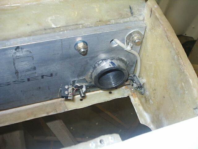
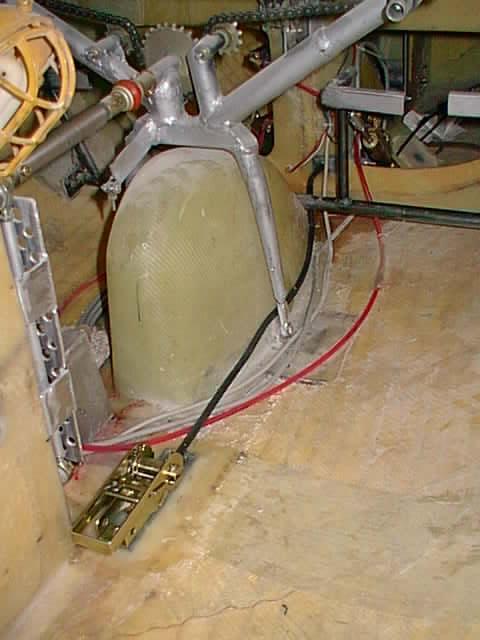
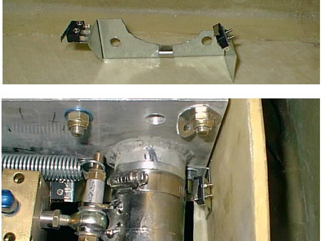 Another thing to install before closing in the upper strake. The up/down
microswitches are shown on galvanized sheet metal bracket fabricated.
I choose galvanized steel since it can be adjusted and can stand a lot
more distortion before breaking - unlike aluminum which breaks after a
few bends. The lower part of photo shows switch assembly in place. The
down switch is activated by end of cylinder while the up switch is
activated by the clamp butt shown when gear retracts. The wiring to switches
is not connected yet.
Another thing to install before closing in the upper strake. The up/down
microswitches are shown on galvanized sheet metal bracket fabricated.
I choose galvanized steel since it can be adjusted and can stand a lot
more distortion before breaking - unlike aluminum which breaks after a
few bends. The lower part of photo shows switch assembly in place. The
down switch is activated by end of cylinder while the up switch is
activated by the clamp butt shown when gear retracts. The wiring to switches
is not connected yet.

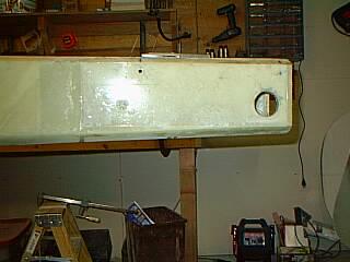
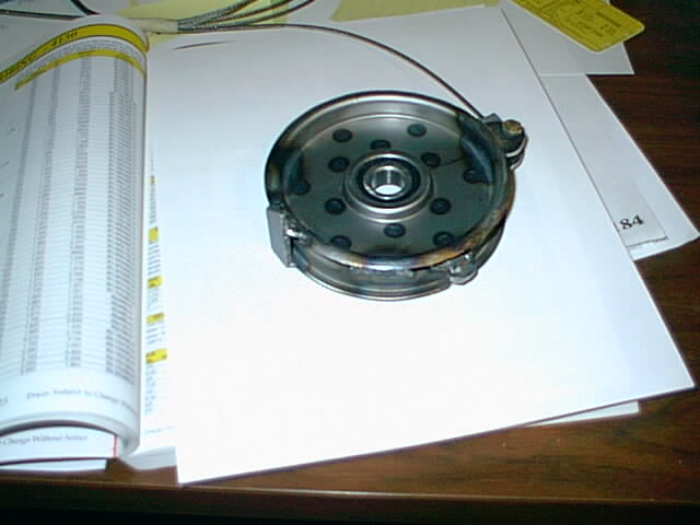
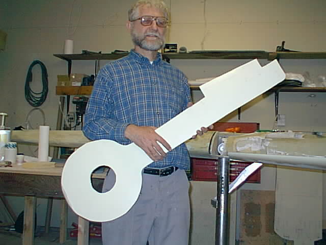 This is not a key. It is the RS cutout from wheel well hole which I use to make
the wheel cover for the retractible. The right side is comming faster than left side
- guess I know more what to do now.
This is not a key. It is the RS cutout from wheel well hole which I use to make
the wheel cover for the retractible. The right side is comming faster than left side
- guess I know more what to do now.
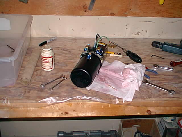 The hydraulic pump performed slugishly on the rg lowering stroke. Apparently
a bit of loose hydraulic hose rubber got into the lines and got mashed by
the pump. Took it appart and clean it and purged the hydraulic lines.
That still didnt do the trick and had it returned to the pump
manufacturer for repairs.
The hydraulic pump performed slugishly on the rg lowering stroke. Apparently
a bit of loose hydraulic hose rubber got into the lines and got mashed by
the pump. Took it appart and clean it and purged the hydraulic lines.
That still didnt do the trick and had it returned to the pump
manufacturer for repairs.
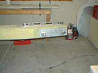
 If there are jobs I dislike, messy hydraulics has got to be on top of the list.
A late note: In the photo you can see the hydraulics sticking up out after the strake was installed. I decided that it would be too hard to service the RG stuff just from below and cutout a cover shape on top (and a small one in front of the RG pivot). Both pieces are held down by screws. I made servicing a priority.
(9/14/04) Do I recommend retracts? A number of SQ2000 builders opted for fixed landing gear rather than retracts. Some other opinions are either all pro's or all con's. Here are the pros and cons I can see.
Pros:
1. More landing stability. The retracts are over 11 ft apart compared to about
6.5 ft fixed gear.
2. The retracts are an effective air brake when extended.
3. Better looks in flight and on ground.
4. Possibly less air resistance than fixed gear.
Cons:
1. More building time.
2. More expensive.
3. Less fuel capacity.
4. More maintenance.
(9/16/05) So far I had to replace 3 springs after a couple of hard landings. One problem is the spring alloy 3" elastic motion limitation (without deformation). But the spring travel allowed by the gear is about 4.25" plus the 1.25" pre-compression required to hold the plane empty. The springs are not difficult to replace or procure - several manufacturers can make them. Stan Montgomery gave me two replacement springs free but the new ones I ordered made of chrome-silicone alloy may last longer. Alternative titanium springs have an elastic working limit of 4.8" but fairly expensive at $600 each and still do not allow for the full 5.5" compression.
AFAIK Infinity Aerospace uses total gas oleo struts which will regulate landing shock better but I suspect may need more gas charge maintenance than spring loaded oleo struts.
(10/04/05) Added extra guide tubing around springs to help retain cylindrical shape when compressed and installed more firmer shocks (Gabriel G63798) with a unique valve system that dampens sudden gear motion on impact.
(06/29/06) Update: It seems that the new chrome-silicon alloy springs and possibly the heavier shocks have prevented further spring sagging. Although I had a RG landing failure 04/13/06, the springs showed no signs of sagging. The new springs were purchased from Associated Spring Raymond (part No.: C200-0406-1400-01A). I recommend their service.