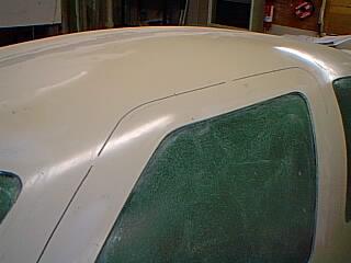
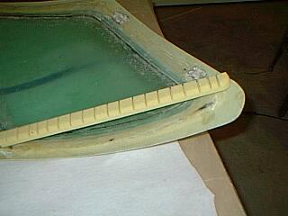
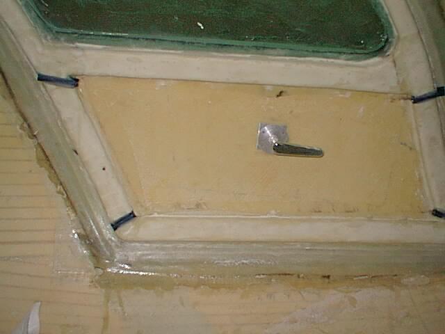
 I cut around the door but left a few spots in to hold the door in place.
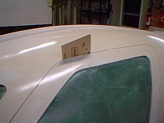 Use the slots to do initial sanding around the door opening (door will be removed
and sanded later)
Use the slots to do initial sanding around the door opening (door will be removed
and sanded later)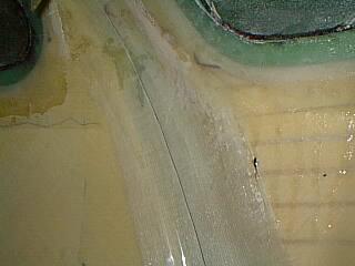 The magic stuff (clear plastic packing tape) is taped over the slot around door - mostly covering the door part
to protect it from resin bonding.
The magic stuff (clear plastic packing tape) is taped over the slot around door - mostly covering the door part
to protect it from resin bonding.
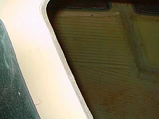
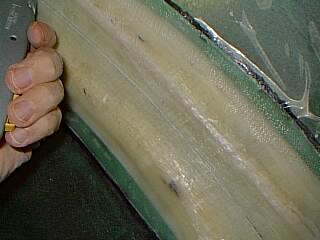 ... and then the tape is cut along through the slot..(bad photo).
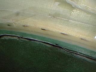 and the portion outside the door is peeled off... hard to see the clear plastic.
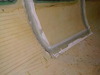
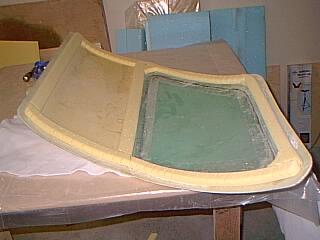
Two 2" glass plies are applied over the frame with less than 0.5" of it reaching over door and then peel plied. When cured the few spots holding door can be cut and door released since the plastic tape cover on doors does not stick to cured resin.
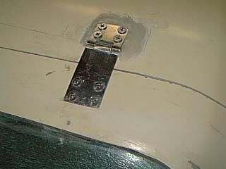
The problem with hinges on SQ2000, is that the door/body border is thin and distance
must be left to clear accross the 5/8" weather strip from the slot so
the only way to get hinges there is to have a surface mount strap type hinge that
reaches sufficiently accross the gap and the hinge pin has to be higher on roof in order to
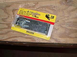
open all part of door away from the body. I ordered a set of Velocity hinges
(as seen below) but they are not long enough to reach across the gap.
I know of some builders who have adapted the Velocity hinges and its
recessed-into-the-roof style. There are two problems I see with that.
First it would mean extending part of the doors into the roof line and going
below ceiling inside - being 6' I need all the ceiling room.
Secondly my over the top strap method does not disturb the roof ply strength.
while the large cut-outs in the roof needed for Velocity hinge style may
weaken the roof structure.
Just an afterthought: Gullwing doors are by design more susceptible to wind dmage when open. The factory hinges are more sturdier than my Kmart solution. However in case of an accident with a door being hit or in a strong wind (or whatever)..., I would prefer the hinges being twisted or broken rather than fuselage damage. It would simply mean a trip to Kmart and some glassing and patching work. But with sturdier factory hinges, even with no fusealage damage, the twisted hinges would be harder to fix/align.
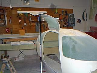
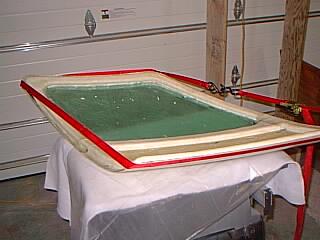
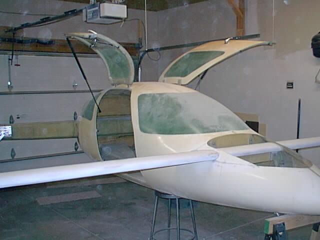
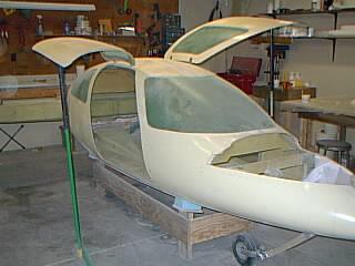 And both doors open.
The foam strips are shown mounted below.
One problem with microballoons mix is that it allways runs. Instead I tried a 3 part mixture of microballoons to 1 part flox which held the stuff reasonably together without running too much.
One thing I wish is to have left the door window installation until
after this point. It is really difficult to deal with epoxy spill
over window part when working so close to windows with these reinforcement
strips.
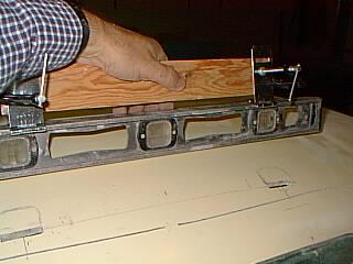
 For some reason when the door is cut out the door shape loses a bit of the curvature
and does not conform exactly to the fuselage. Puting a strap on the door when the
reinforcement glass is curing helps to put the original curve back.
For some reason when the door is cut out the door shape loses a bit of the curvature
and does not conform exactly to the fuselage. Puting a strap on the door when the
reinforcement glass is curing helps to put the original curve back.
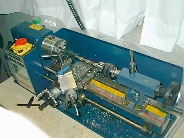
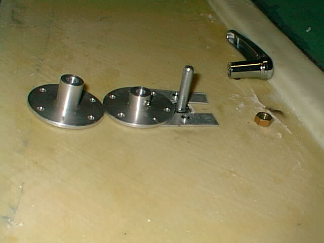 The door knob stem was on the short side. Instead of using the extra stem nut to tighten
door cam to position, I shortened the cam height (my small metal lathe is a real help here)
and installed a set screw to lock the cam into position instead. That left sufficient
stem to attach the inside door knob.
The door knob stem was on the short side. Instead of using the extra stem nut to tighten
door cam to position, I shortened the cam height (my small metal lathe is a real help here)
and installed a set screw to lock the cam into position instead. That left sufficient
stem to attach the inside door knob.
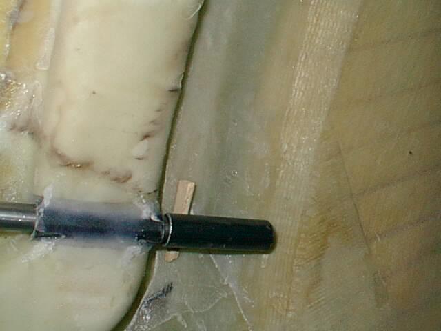 Before floxing/glassing outer sleeves, with the door in place and the pins in, the outer sleeve
is pushed into the fuselage with a small wooden wedge. That ensures a tight door fit.
Before floxing/glassing outer sleeves, with the door in place and the pins in, the outer sleeve
is pushed into the fuselage with a small wooden wedge. That ensures a tight door fit. I also intend to put a small metal guide for each door as found in automobiles so that the door goes exactly in position where it should.
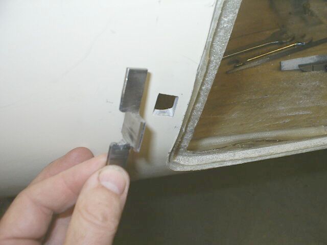
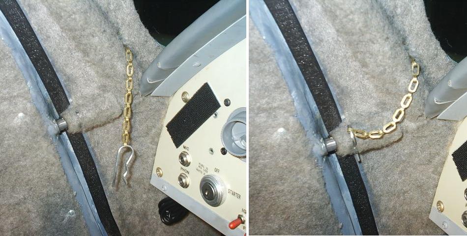
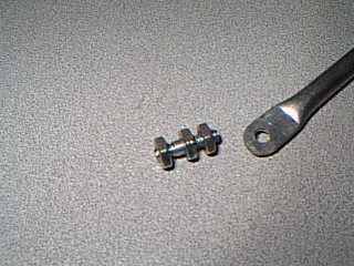
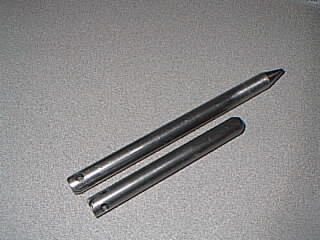
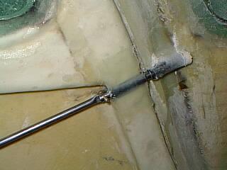
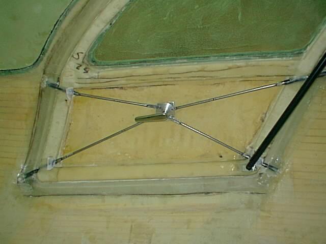
A good way to install the door pins for minimum length is to fit them in the door with cam in closed position and the pins into sleeves almost as far as they will go (fourth photo in this group). Then I rotated the cams into open position and marked the door pin cutoff size - then hacksaw, grinding, sanding pins tips.... The third photo here shows the alternating over/under door rod positioning required since the cam pins interfere with each other's rods in open position. The rods are easy to shape - the ends are simply squeezed flat with a wise and holes are drilled for the cam pins and door pins.
NOTE: Floxing the door cam stud threads before installation onto cam makes an excellent thread lock so that the nuts do not work loose.
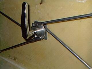
 Door strut mounting: The gas strut mount is held in place with a small wooden spacer away from the door
weather mount while the flox/glass is curing. For even gas strut mounting only one
of these should be mounted/cured first - the strut mounts on the door can be glassed
both right away and all in one session using a small clamp over the mount and glass
plies. As mentioned before, the fuselage halves were not perfectly matched
so that mounting the strut door mounts at recommended position would make
doors look lopsided in the open position.
Instead, only one side is placed (along with both door mounts) and then after curing
the other strut door mount can be positioned so that the doors look even when open.
I found that such "symmetric" height appearance required left
door mount to be placed about 1 inch lower from recommended position.
Door strut mounting: The gas strut mount is held in place with a small wooden spacer away from the door
weather mount while the flox/glass is curing. For even gas strut mounting only one
of these should be mounted/cured first - the strut mounts on the door can be glassed
both right away and all in one session using a small clamp over the mount and glass
plies. As mentioned before, the fuselage halves were not perfectly matched
so that mounting the strut door mounts at recommended position would make
doors look lopsided in the open position.
Instead, only one side is placed (along with both door mounts) and then after curing
the other strut door mount can be positioned so that the doors look even when open.
I found that such "symmetric" height appearance required left
door mount to be placed about 1 inch lower from recommended position.I also do not like the doors so high in open positon as it is harder to reach for closing in seating position and so will probably replace the struts with slightly shorter ones.
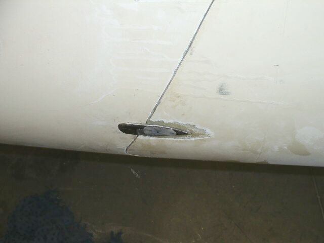
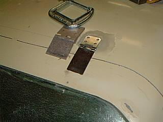
One of the nagging problems was the doors would sag somewhat and would essentially require "a little manual lift" into place when closing. I thought about making a striking plate / plunger guide like found on cars but until now could not figure a convenient spot for mounting it to make sure it does not get in the way or cause a bruise/injury. I finally settled on the lower front door outside position a few inches above the inside door closing plunger. The illustrations below may be left or right side since one was curing when working with other.
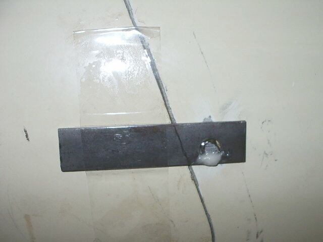
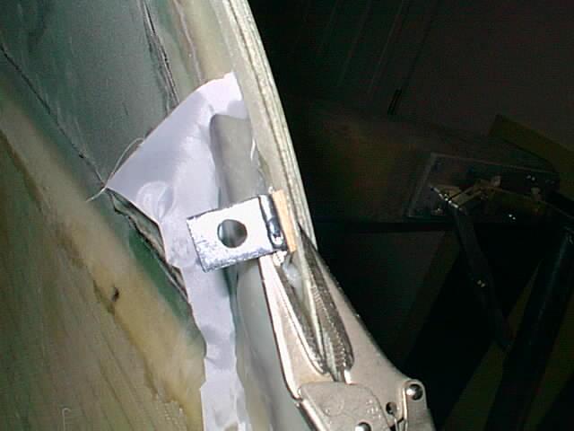
The striking plate is made up of 3/32 x 3/4 x 1 steel plate with some
winglets attached (welded) for glassing from inside. It is fitted from inside
into the 1/2 x 3/4 hole and the extra protrusion cut off and sanded.
The striking plate extends about 7/8" into the fuselage.
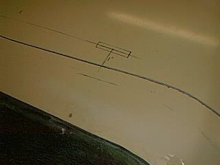
To have the plunger slide
properly out of the door its axis and the the striking plate surface
is parallel to the door cutout line and faces front of the aircraft - and not
perpendicular to the outside surface (the surface is not parallel to hinge line).
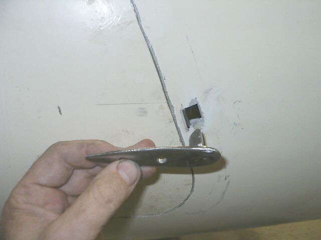
The outside plunger assembly is made up of a 1 x 3/8 x 3/8 keyway steel rounded
a little at one end - it is jammed into correct position by a small wood wedge -
and a 1 x 1/8 plate steel with a bigger hole near front/bottom. The plate is
bent to match fuselage curve at gap and taped over the plunger and floxed
(using Wal-Mart fast super-poxy) into position, then taken out and fill welded
in the gap. The final streamline shape is about 3.75" long and the front
part just covers the square hole.
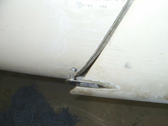
If doing this make sure you get the orientations correct (remember that the
motion is perpendicular to the line of the hinges) otherwise the
result may jam up when trying to open the doors. The square plunger should
be at the bottom of the striker plate hole ( because it goes UP when opened)
and flat/square against the striker plate surface. A little fiberglass cap
is glassed from inside over the hole to keep any drafts out. After painting
the result should be hardly noticeable being fairly small by comparison.
The modification helps the door line up perfectly and a little grease in the
hole will make things last. Some of you visual perfectionists may not like
the small protrusion but other alternatives I see as tremendous amount of work
and not really working better. The location of the device helps to support
the door in a balanced way.